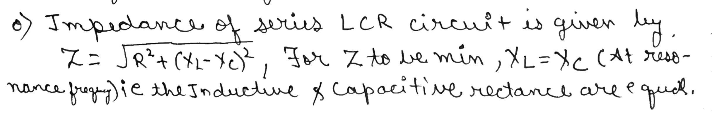
Alternating Current - Class 12 Medical Physics - Extra Questions
In a series LCR circuit, obtain an expression for the resonant frequency.
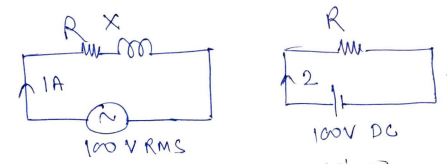
When a series combination of inductance and resistance are connected with a $$10V.50Hz$$ a.c source, a current of $$1A$$ flows in the circuit.The voltage leads the current by phase angle of $$\cfrac { \pi }{ 3 } $$ radian. Calculate the values of resistance and inductive reactance.
Calculate the impedance of a condenser in order to run a bulb rated at 10 watt and 60 volt when connected in series to an A.C.Source of 100 volt.
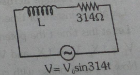
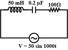
The current in the shown circuit is found to be $$4 \sin\left(314t-\dfrac{\pi}{4}\right)A$$. Find the value of inductance.

An alternating voltage$$ E=200 \,sin \,(300t)$$ volt is applied across a series combination of $$R=10 \Omega$$ and inductance of $$800\ mH$$. Calculate the impedance of the circuit.
A coil of reactance $$100 \Omega$$ and resistance $$100 \Omega$$ is connected to a 240 V, 50 Hz a.c. supply. Find the impedance of the circuit.
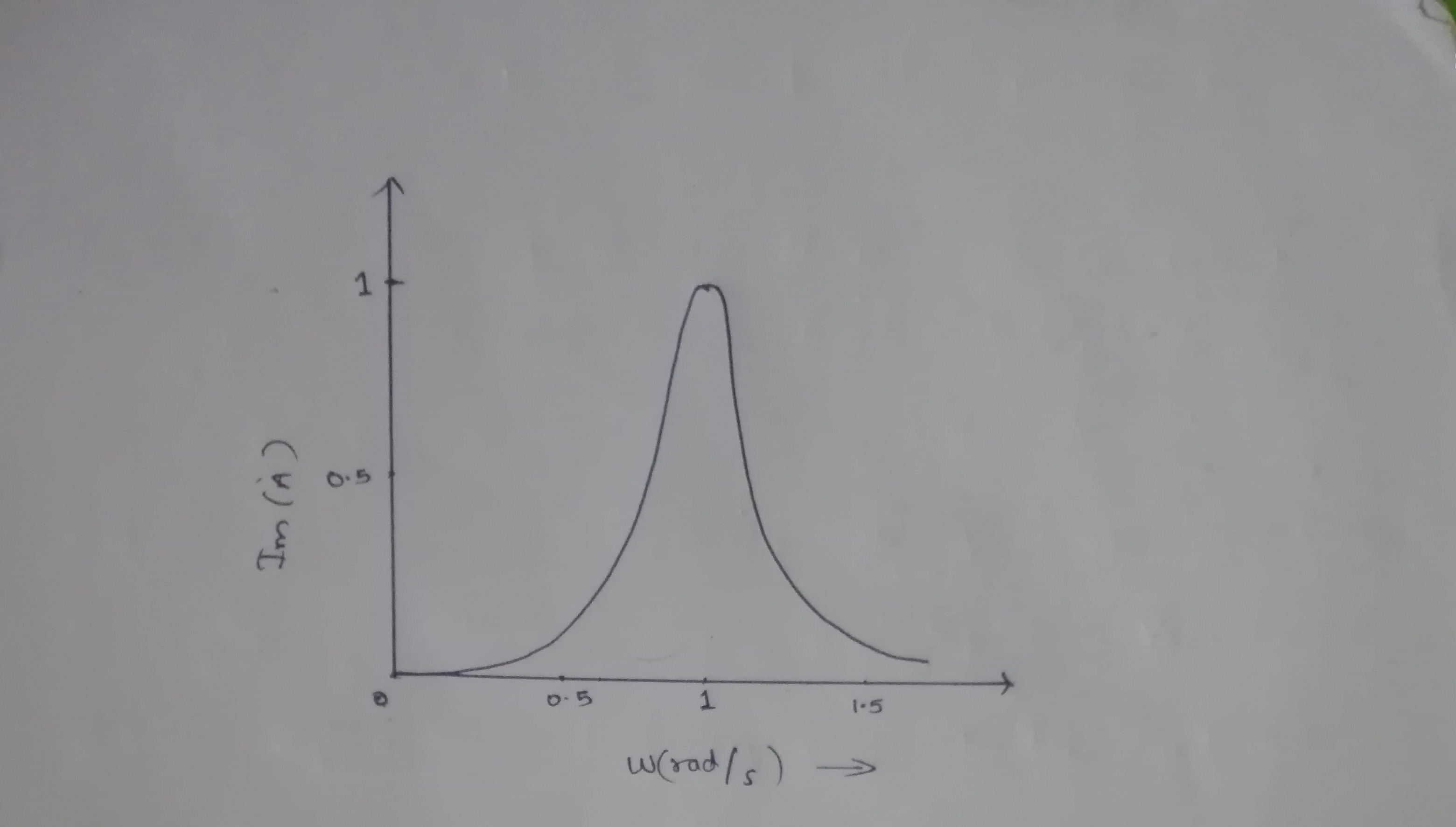
Draw the graph of $$I_{rms} \rightarrow \omega$$ for an A.C., L-C-R series circuit and hence explain Q-factor.
The graph shows variation of current $$I_{rms}$$ with angular frequency $$\omega$$
The Q factor is a dimensionless parameter that indicates the energy losses within a resonant element which could be anything from a mechanical pendulum, an element in a mechanical structure or within electronic circuit such as resonant circuit.
The current in the shown circuit is found to be $$4\sin { \left( 314t-\cfrac { \pi }{ 4 } \right) A } $$. Find the value of inductance.
A $$ 15.0\ \mu\ F$$ capacitor is connected to a $$220\ V, 50\ Hz$$ source. Find the capacitive reactance and the current (rms and peak) in the circuit. If the frequency is doubled , what happens to the capacitive reactance and the current ?
A capacitor of capacitance $$0.5\ \mu F$$ is connected to a source of alternating electromagnetic force of frequency $$100\ Hz$$. What is the capacitive reactance? ($$\pi = 3.142$$)
An AC rms voltage of $$2V$$ having a frequency of $$50\ KHz$$ is applied to a condenser of the capacity of $$10\mu F$$. The maximum value of the magnetic field between the plates of the condenser if the radius of a plate is $$10 cm$$ is _____.
Calculate Impedance of the circuit at the given frequency.
Calculate inductive reactance of coil in the following figure.

Using the expressions for charge and current for L-C oscillator, explain L-C oscillations.
In the circuit diagram shown, $$X_C=100 \Omega,X_L=200 \omega$$ and $$R=100 \omega$$. Find the effective current through the source.
What do you mean by resonance in $$LCR$$ series circuit? Write the formula for resonant frequency.
An alternating voltage $$E = 200\sin 300t$$ is applied across a series combination of $$R = 10\ ohm$$ and an inductor of $$800\ mH$$ calculate.
(i) impedance of the circuit.
(ii) Peak value of current in the circuit.
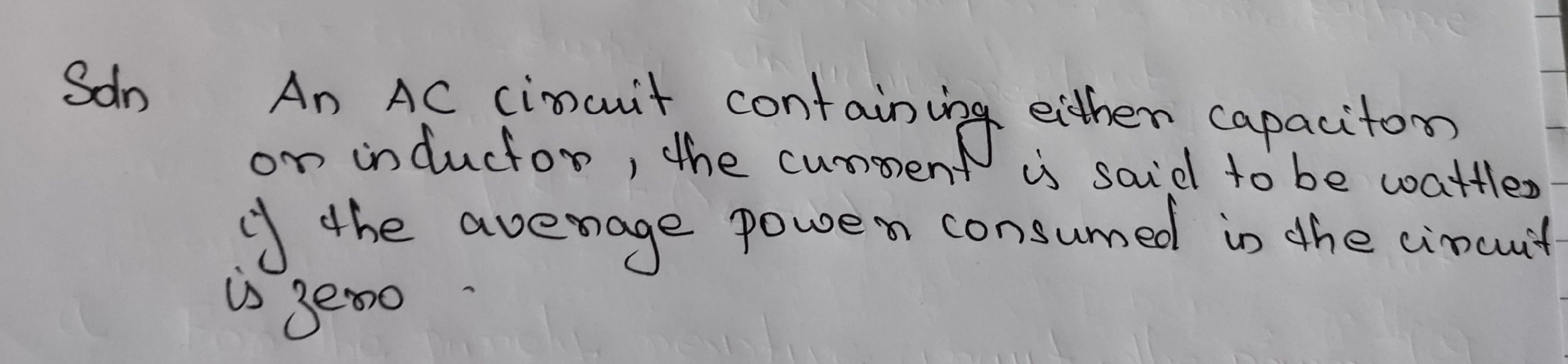
What is wattles current?
A series $$LCR$$ circuit has an inductance of $$100\ mH$$, a capacitor $$0.1\mu F$$ and a resistance of $$200\Omega$$. Find the impedance at resonance and the resonant frequency.
An inductor $$2/\pi $$ F and a resistor $$100/\pi $$ are connected in series across a source of emf v=$$10$$sin $$100$$ [$$\pi$$ t]. Here t is in second. (a) find the impedance of the circuit find the energy dissipated in the circuit in $$20$$ minutes.
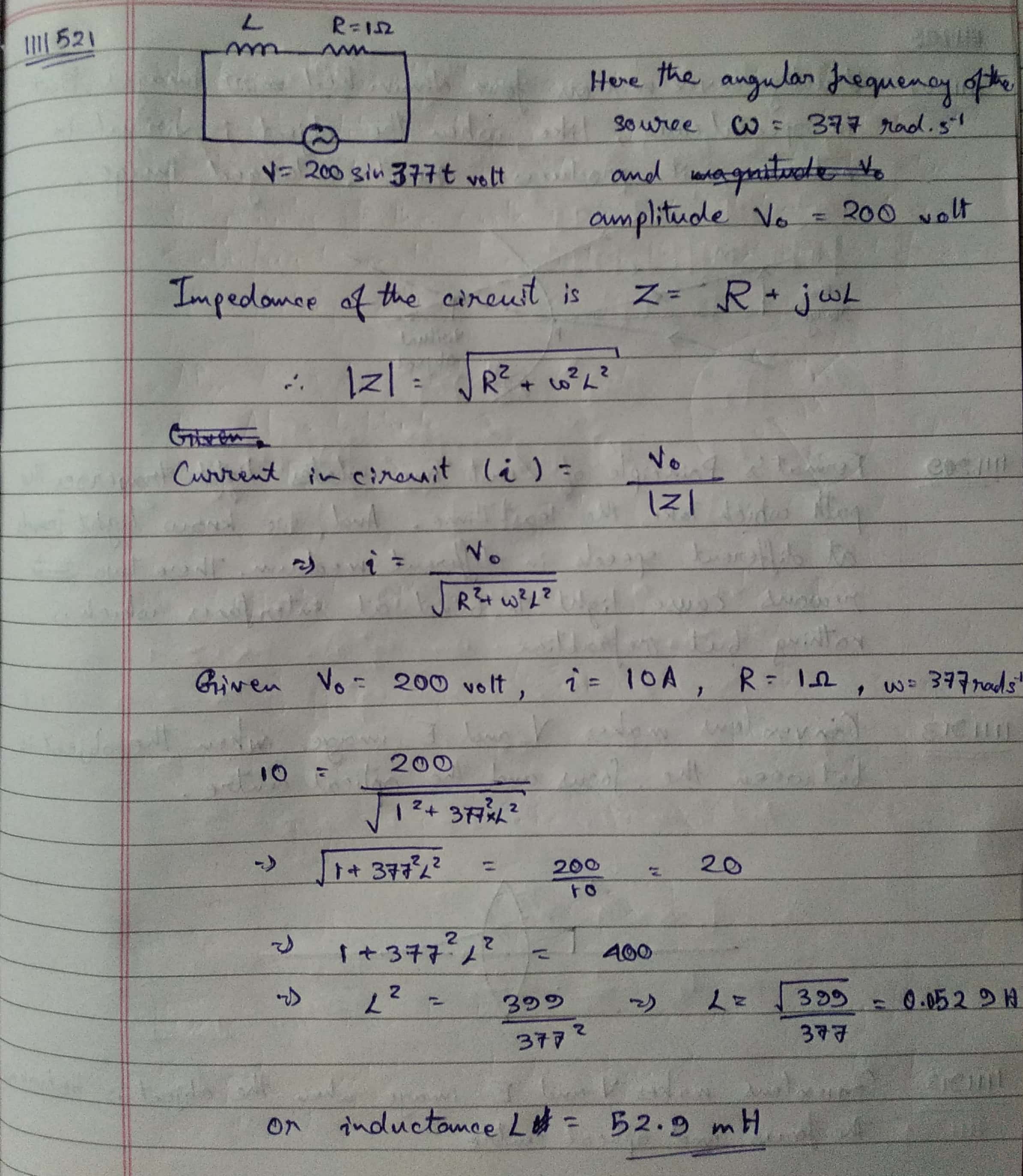
A voltage V = 200 sin 377 t volt is applied across an inductance L having a resistance of $$ 1.0 \Omega $$ The maximum current is found to be 10 A. Find the value of L.
Calculate the total reactance if two inductor of 10mH and 50 mH are connected in series with 10 kHz AC.
A sinusodial voltage of peak value 283 V and frequency 50 Hz i applied across a LCR circuit in which $$ R = 3 \Omega$$ $$L = 25.48\space mH$$ $$ C = 796 \space \mu F$$. Find the impedance of the circuit.
Explain the production of the electrical oscillation in LC circuit. Under what conditions are the oscillation produce in the circuit.
A $$20\Omega$$ resistor, $$1.5$$H inductor and $$35\mu F$$ capacitors are connected in series with $$200$$V, $$50$$Hz ac supply. Calculate the impedance of the circuit and also find the current through the circuit?
If an LC circuit has $$ C= 1\mu F $$ & $$ L = 0.25 $$ henry. neglecting any resistance in the circuit, what is the frequency of oscillation ?
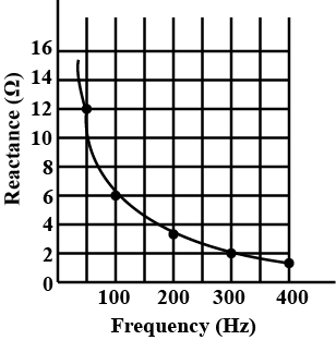
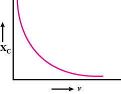
The figure shows the graphical variation of the reactance of a capacitor with frequency of ac source.
Find the capacitance of the capacitor.

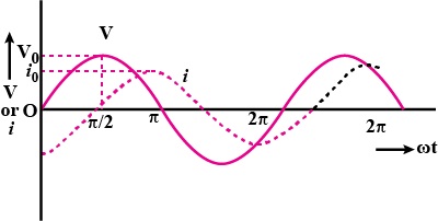
An ac source of emf $$V = V_0 \, \sin \omega t$$ is connected to a capacitor of capacitance C. Deduce the expression for the current (I) flowing in it. Plot the graph of (i) V vs $$\omega t$$, and (ii) I vs. $$\Omega t$$.
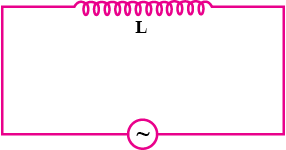
Show that in an $$AC$$ circuit containing a pure inductor, the voltage is ahead of current by $$\pi /2$$ in phase
Answer in brief:
What is the natural frequency of the LC circuit? What is the reactance of this circuit at this frequency?
Alternating $$emf$$ of $$e = 220\sin 100 \pi t$$ is applied to a circuit containing an inductance of $$(1/\pi)henry$$. Write an equation for instantaneous current through the circuit. What will be the reading of the $$AC$$ galvanometer connected in the circuit?
How soon does the current amplitude in an oscillating circuit with quality factor $$Q=5000$$ decrease $$\eta =2.0$$ times if the oscillation frequency is $$\nu=2.2MHz$$?
Conceptual Questions
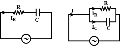
(a) Why does a capacitor act as a short circuit at high frequencies?
(b) Why does a capacitor act as an open circuit at low frequencies?
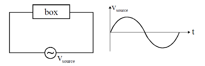
Box may have any series combination of L, C and R. Column-I represents source current and column-II represents possible statements.
If a $$0.03H$$ inductor, a $$10\Omega$$ resistor and a $$2\mu F$$ capacitor are connected in series. it is observed that they resonate at frequency of 325 $$\times$$ s Hz. Find the value of s.
An electric lamp which runs at $$100V$$ dc and consumes $$10A$$ current is connected to ac mains at $$150V, 50 Hz$$ cycles with a choke coil in series. The inductance of voltage across the choke is given as $$x\times 10^{-3} H$$.Find $$x$$ Neglect the resistance of choke.
What is the reactance in ohms of a $$2.00H$$ inductor at a frequency of $$50.0Hz$$?
Match the following two columns:
A series LCR circuit with R = 20 $$\Omega$$ , L = 1.5 H and C = 35 $$\mu$$F is connected to a variable-frequency 200 V ac supply. When the frequency of the supply equals the natural frequency of the circuit, what is the average power transferred to the circuit in one complete cycle?
A 44 mH inductor is connected to 220 V, 50 Hz ac supply. Determine the rms value of the current in the circuit.
A radio can tune over the frequency range of a portion of MW broadcast band: (800 kHz to 1200 kHz). If its LC circuit has an effective inductance of 200 $$\mu$$H, what must be the range of its variable capacitor?[Hint: For tuning, the natural frequency i.e., the frequency of free oscillations of the LC circuit should be equal to the frequency of the radiowave.]
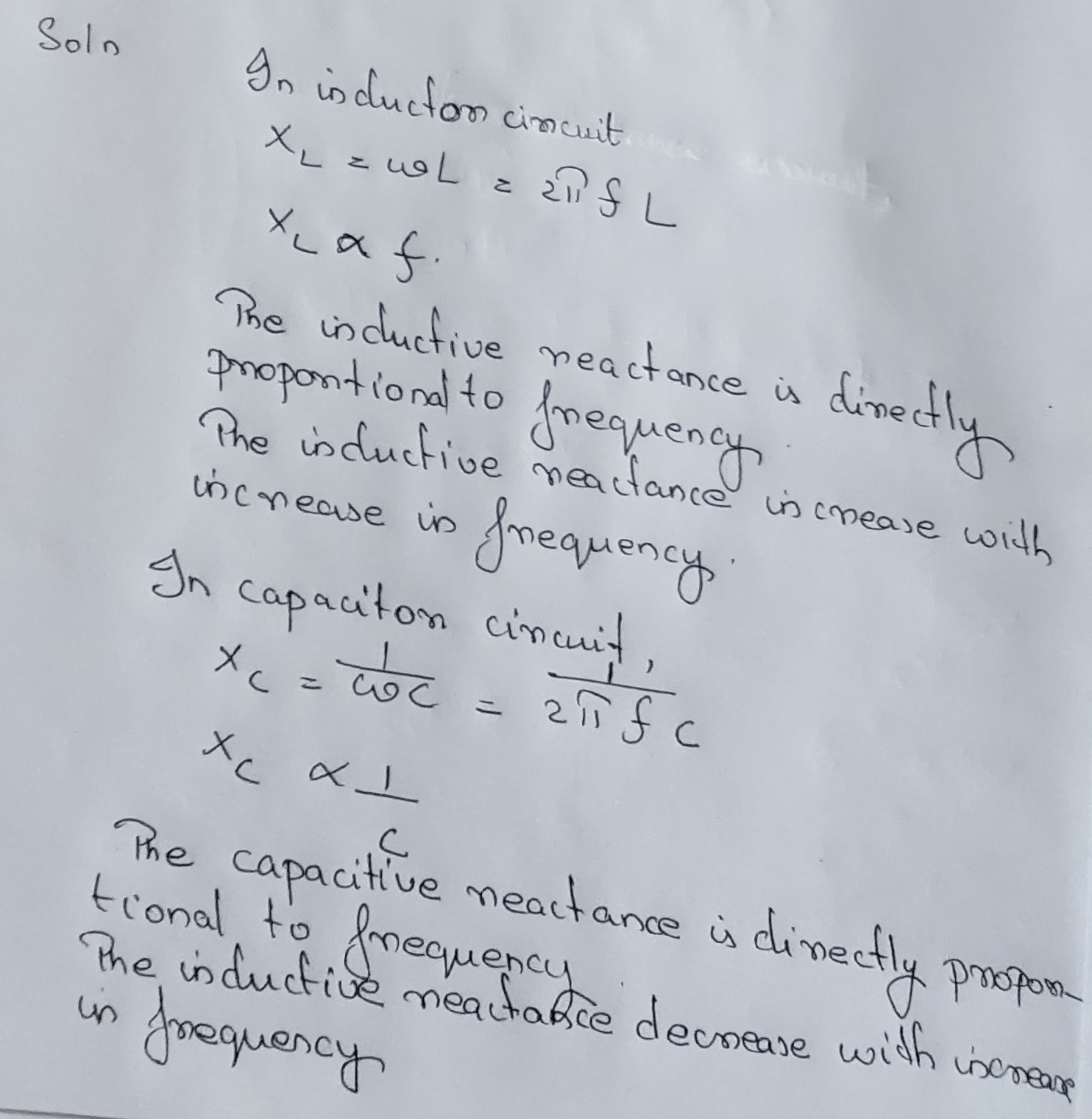
What will be the effect on Inductive reactance $$X_{L}$$ and capacitive reactance $$X_{C}$$ if frequency of ac source is increased?
What is meant by wattless component of the current?
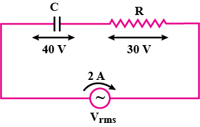
In the given circuit, the potential difference across the inductor $$L$$ and resistor $$R$$ are $$200 V$$ and $$150 V$$ respectively and the rms value of current is $$5 A$$. Calculate the impedance of the circuit.
Calculate the resonant frequency and Q-factor (Quality factor) of a series L-C-R circuit containing a pure inductor of inductance 4 H, capacitor of capacitance $$27\mu F$$ and resistor of resistance $$8\cdot 4\Omega$$
For an A.C. circuit containing an inductance L, a capacitance C and a resistance R connected in series, establish the formula for impedance of the circuit and write the relationship between the alternating e.m.f. and currents in each of the following case when :
(i) $$ w L>\displaystyle\frac{1}{\omega C}$$,
(ii) $$w L<\displaystyle\frac{1}{\omega C}$$,
(iii) $$w L=\displaystyle\frac{1}{\omega C}$$.
Calculate resonant frequency and Q-factor of a series L-C-R circuit containing a pure inductor of inductance 3 H, Capacitor of capacitance $$27\mu F$$ and resistor of resistance $$7.4\Omega$$.
Calculate Impedance of the given ac circuit.

What is the power dissipated by an ideal inductor in ac circuit? Explain.
Distinguish between the terms effective value and peak value of alternating current.
You are given many resistances, capacitors and inductors. These are connected to a variable $$DC$$ voltage source (the first two circuits) or an $$AC$$ voltage source of $$50\ Hz$$ frequency (the next three circuits) in different ways as shown in List $$2$$. When a current I (steady state for $$DC$$ or rms for $$AC$$) flows through the circuit, the corresponding voltage $$V_{1}$$ and $$V_{1}$$. (indicated in circuits) are related as shown in List $$1$$.Match the two
Answer the following:
What is the impedance of a capacitor of capacitance C in an AC circuit using source of frequency n Hz?
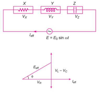
When a circuit element $$X$$ is connected across an a.c. source, a current of $$\sqrt{2} A$$ flows through it and this current is in phase with the applied voltage. When another element $$Y$$ is connected across the same a.c. source, the same current flows in the circuit but it leads the voltage by $$\dfrac{\pi}{2}$$ radians. Name the circuit element $$X$$ and $$Y$$.
An alternating current of frequency $$\omega =314s^{-1}$$ is fed to a circuit consisting of a capacitor of capacitance $$C=73\mu F$$ and an active resistance $$R=100\Omega$$ connected in parallel. Find the impedance of the circuit.
An oscillating circuit consist of a capacitor with capacitance $$C=1.2nF$$ and a coil with inductance $$L=6.0\mu H$$ and active resistance $$R=0.50\Omega$$. What mean power should be fed to the circuit to maintain undamped harmonic oscillations with voltage amplitude across the capacitor being equal to $$V_m=10V$$?
If a circuit made up of a resistance $$1 \Omega$$ and inductance 0.01H, and alternating emf 200 V at 50 H is connected, then the phase difference between the current and the emf in the circuit is :
The current is given as $$\dfrac{x}{10} A$$. Find $$x$$
An $$L-C-R$$ series circuit with $$L=0.120H, R=240\Omega$$, and $$C=7.30\mu F$$ carries an rms current of $$0.450A$$ with a frequency of $$400Hz$$. What is the average rate at which electrical energy is dissipated (converted to other forms) in the inductor?
An $$L-C-R$$ series circuit with $$L=0.120H, R=240\Omega$$, and $$C=7.30\mu F$$ carries an rms current of $$0.450A$$ with a frequency of $$400Hz$$. The average rate at which electrical energy is converted to thermal energy in the resistor is given as $$\dfrac{x}{10} W$$. Find $$x$$
Power losses in case of ac (in W) is
A charged 30 $$\mu$$F capacitor is connected to a 27 mH inductor. What is the angular frequency of free oscillations of the circuit?
The reactance of a $$2.00\mu F$$ capacitor at a frequency of $$50.0Hz$$ is $$\dfrac{x}{10}k\Omega$$. Find $$x$$
The capacitance of a capacitor whose reactance is $$2.00\Omega$$ at $$50.0Hz$$ is $$\dfrac{x}{10}mF$$ Find $$x$$
A circuit operating at $$\displaystyle \frac{360}{2\pi}Hz$$ contains a $$1\mu F$$ capacitor and a $$20\Omega$$ resistor. How large an inductor must be added in series to make the phase angle for the circuit zero? Calculate the current (in A) in the circuit if the applied voltage is $$120V$$.
Write value of $$\dfrac{L}{1.1}+I$$.
The inductance of an inductor whose reactance is $$2.00\Omega$$ at $$50.0Hz$$ is $$\dfrac{x}{100} mH$$. Find $$x$$
Define capacitor reactance. Write its S.I. units
What is the phase difference between AC e.m.f and current in the following?
Pure resistor and pure inductor.
Alternating current flowing through a certain electrical device leads over the potential difference across it by $$90^{\circ}$$. State whether this device is a resistor, capacitor or an inductor
In modern days incoming frequency of radio receiver is superposed with a locally produced frequency produce intermediate frequency which is always constant. This makes tuning of the receiver very simple. This is used in superheterodyne oscillators.
A light bulb is rated at $$100W$$ for a $$220V$$ ac supply. Calculate the resistance of the bulb.
When 10V, DC is applies across a coil current through it is 2.5 A, if 10V, 50Hz A. C. is applied current reduces to 2 A. Calculate reluctance of the coil.
An ac source of angular frequency $$\omega$$ is fed across a resistor $$R$$ and a capacitor $$C$$ in series. The current registered is $$I$$. If now the frequency of source is changed to $$\omega/3$$ (but maintaining the same voltage), the current in the circuit is found to be halved. The ratio of the reactance to resistance at the original frequency $$\omega$$ is given as $$\sqrt{\displaystyle\frac{x}{5}}$$. Find $$x$$
A $$9/100\pi$$ inductor and a $$12\omega$$ resistance are connected in series to a $$225\space V, \space 50\space Hz$$ ac source. Calculate the current (in $$A$$) in the circuit.
If the inductance of the choke coil is $$x\times10^{-4}H$$. Find $$x$$
A coil of inductance $$0.50\space H$$ and resistance $$100\Omega$$ is connected to a $$240\space V,\space 50\space Hz$$ ac supply. The maximum current in the coil is given as $$\dfrac{x}{100} A$$. Find $$x$$.
A $$100\space \mu F$$ capacitor in series with a $$40\space \Omega$$ resistor is connected to a $$110\space V, \space 60\space Hz$$ supply. The maximum current in the circuit is $$x\times 10^{-2} A$$. Find $$x$$.
Leading is $$\dfrac{x}{1000}H$$
Match the following column
In the circuit shown in figure, match the following two columns. In column $$II$$ quantities are given in $$SI$$ units.
A $$300\Omega$$ resistor is connected in series with a $$0.800H$$ inductor. The voltage across the resistor as a function of time is $$V_R=(2.50V)\cos[(950 rad/s)t]$$. Determine the inductive reactance of the inductor.
Power loss (in W) in case of dc is
An $$L-C-R$$ series circuit with $$L=0.120H, R=240\Omega$$, and $$C=7.30\mu F$$ carries an rms current of $$0.450A$$ with a frequency of $$400Hz$$. What is the impedance of the circuit?
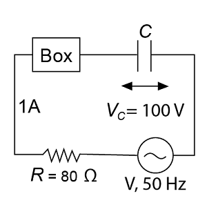
A circuit element shown in the figure as a box is having either a capacitor or an inductor. The power factor of the circuit is $$0.8$$, which current lags behind the voltage. The source voltage $$V$$,
What is meant by rms (effective) value of alternating current?
(a)The pointer in the galvanometer deflects, when a bar magnet pushed or away from the coil connected to a galvanometer. Identify the phenomenon causing this deflection and write the factors on which the amount and direction of the deflection depends. State the laws describing this phenomenon.
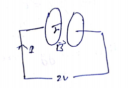
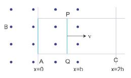
(b) Sketch the change in flux, emf and force when a conducting rod PQ of resistance R and length l moves freely to and fro between A and C with speed v on a rectangular conductor placed in uniform magnetic field as shown in the figure.
a) When the magnet shown below is moved “towards” the coil, the pointer or needle of the Galvanometer, which is basically a very sensitive center, will deflect away from its center position in one direction only. When the magnet stops moving and is held stationary with regards to the coil the needle of the galvanometer returns back to zero as there is no physical movement of the magnetic field. This is as per Michael Faraday’s law of electromagnetic induction which states: “that a voltage is induced in a circuit whenever relative motion exists between a conductor and a magnetic field and that the magnitude of this voltage is proportional to the rate of change of the flux”.
Factors on which amount and direction of deflection depends are as under-
1) Increasing the number of turns of wire in the coil. – By increasing the amount of individual conductors cutting through the magnetic field, the amount of induced emf produced will be the sum of all the individual loops of the coil.
2) Increasing the speed of the relative motion between the coil and the magnet. – If the same coil of wire passed through the same magnetic field but its speed or velocity is increased, the wire will cut the lines of flux at a faster rate so induced emf would be produced.
3) Increasing the strength of the magnetic field. – If the same coil of wire is moved at the same speed through a stronger magnetic field, there will be more emf produced because there are more lines of force to cut.
b)
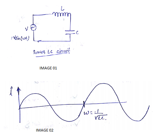
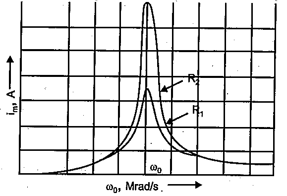
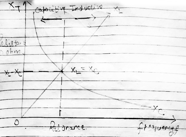
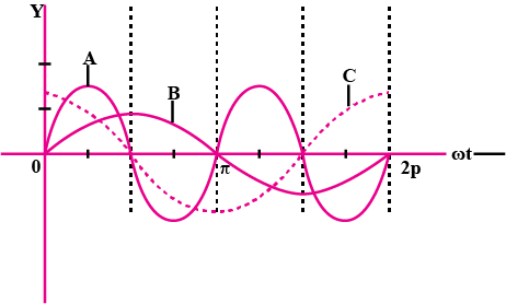
In a series LCR circuit connected to an ac source of variable frequency and voltage $$v=v_{m}sin\omega t$$, draw a plot showing the variation of current (I) with angular frequency $$(\omega)$$ for two different values of resistance $$R_{1}\;and \;R_{2}(R_{1}>R_{2})$$, Write the condition under which the phenomenon of resonance occurs. For which value of the resistance out of the two curves a sharper resonance is produced? Define Q-factor of the circuit and give its significance
The condition for resonance in the LCR circuit is,
$$\displaystyle \omega_{0}=\frac{1}{\sqrt{LC}}$$
We can observe that the current amplitude is maximum at the resonant frequency $$\omega$$. Since $$i_{m}=V_{m}lR$$ at resonance, the current amplitude fro case $$R_{2}$$ is sharper to that for case $$R_{1}$$ Quality factor or simply the Q-factor of a resonance LCR circuit is defined as the ratio of voltage drop across the capacitor (or inductor ) to that of applied voltage
It is given by $$Q=\frac{1}{R}\sqrt{\frac{L}{C}}$$
The Q factor determines the sharpness of the resonance curve and if the resonance is less sharp, the maximum current decrease and also the circuit is close to the resonance for a larger range $$\Delta \omega $$ of frequencies and the regulation of the circuit will not be good. So, less sharp the resonance, less is the selectivity of the circuit while higher is the Q, sharper is the resonance curve and lesser will be the loss in energy of the circuit
An alternative voltage given by $$V=140( \sin{314} t)$$ is connected across a pure resistor of $$50 \Omega$$. Find
(i) The frequency of the source.
(ii) The rms current through the resistor.
Adjoining figure shows a series $$RCL$$ circuit connected to an ac source which generates an alternating emf of frequency $$50\ Hz$$. The reading of the voltmeters $$V_{1}$$ and $$V_{2}$$ are $$80\ V$$ and $$60\ V$$ respectively.
Find:
The current in the circuit

At resonance, what is the relation between impedance of a series $$LCR$$ circuit and its resistance $$R$$?
Adjoining figure shows a series $$RCL$$ circuit connected to an ac source which generates an alternating emf of frequency $$50\ Hz$$. The reading of the voltmeters $$V_{1}$$ and $$V_{2}$$ are $$80\ V$$ and $$60\ V$$ respectively.
Find:
The capacitance $$C$$ of the capacitor

Impedance of the circuit
Inductive reactance
In an alternating circuit applied voltage is $$220V$$. If $$R=8\Omega$$, $${X}_{L}={X}_{C}=6\Omega$$ then write the values of the following:
(a) Root mean square value of voltage.'
(b) Impedance of circuit.
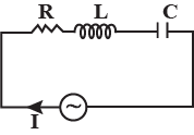
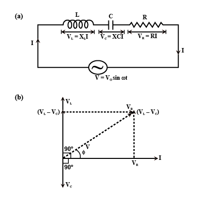
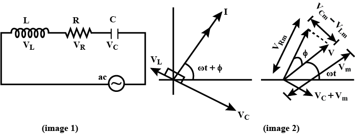
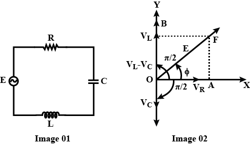
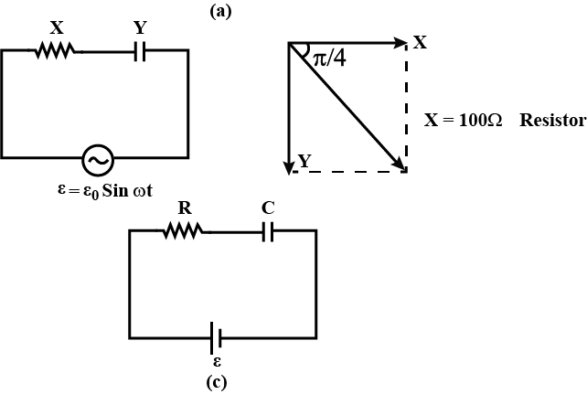
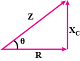
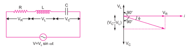
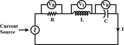
Arrive at the expression for the impedance of a series $$LCR$$ circuit using phasor diagram method and hence write the expression for the current through the circuit.
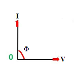
Let the current through the series be $$i={ i }_{ m }\sin { \left( \omega t+\phi \right) } $$
where $$\phi $$ is phase difference between voltage and current. (Ref. image 1)
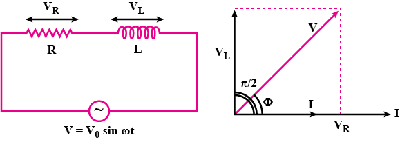
Let $$\vec {I} $$ be the phasor representing current and $${ \vec { V } }_{ R },{ \vec { V } }_{ L },{ \vec { V } }_{ C }$$ and $${ \vec { V } }$$ be the phasors representing voltage across $$R,L,C$$ and source respectively and we assume that $${ \vec { V } }_{ C }> { \vec { V } }_{ L }$$. (Ref. image 2)
The length of the phasors $${ \vec { V } }_{ R },{ \vec { V } }_{ L },{ \vec { V } }_{ C }$$ are
$${ V }_{ Rm }={ i }_{ m }R\quad $$
$${ V }_{ cm }={ i }_{ m }{ X }_{ C }$$ and
$${ V }_{ Lm }={ i }_{ m }{ X }_{ L }$$
From Kirchhoff's loop rule $$V_L+V_R+V_C=V$$
and the phasor relation is represented as,
$${ \vec { V } }_{ L }+{ \vec { V } }_{ R }+{ \vec { V } }_{ C }\quad ={ \vec { V } }$$
Expression for Impedence:
Applying Pythagorean Theorem to the right angle triangle,
$${ V }_{ m }^{ 2 }={ V }_{ Rm }^{ 2 }+{ \left( { v }_{ cm }-{ v }_{ Lm } \right) }^{ 2 }$$
$${ V }_{ m }^{ 2 }={ \left( { i }_{ m }R \right) }^{ 2 }+{ \left( { i }_{ m }{ X }_{ c }-{ i }_{ m }{ X }_{ L } \right) }^{ 2 }\quad $$
$${ V }_{ m }^{ 2 }={ i }_{ m }^{ 2 }\left[ { R }^{ 2 }+{ \left( { X }_{ c }-{ X }_{ L } \right) }^{ 2 } \right] \quad $$
$${ V }_{ m }={ i }_{ m }\sqrt { { R }^{ 2 }+{ \left( { X }_{ c }-{ X }_{ L } \right) }^{ 2 } } \quad \quad $$
$${ i }_{ m }=\cfrac { { V }_{ m } }{ \sqrt { { R }^{ 2 }+{ \left( { X }_{ c }-{ X }_{ L } \right) }^{ 2 } } } $$
$${ i }_{ m }=\cfrac { { V }_{ m } }{ Z } $$
Where $$Z$$ is called impedance of the coil
$$Z=\sqrt { { R }^{ 2 }+{ \left( { X }_{ c }-{ X }_{ L } \right) }^{ 2 } } $$
A $$20$$ volt $$5$$ watt lamp is used on a.c mains of $$200$$ volts $$50$$ c.p.s. Calculate the value of
(a) capacitance (b) inductance to be put in series to run the lamp
(c) how much pure resistance should be included in place of the above device so that lamp can run on its voltage?
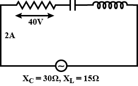
$$200V$$ A.C is applied at the ends of an LCR circuit. The circuit consists of an inductive reactance $${X}_{L}=50\Omega$$, capacitive reactance $${X}_{C}=50\Omega$$ and ohmic resistance $$R=10\Omega$$. Calculate the impedance of the circuit and also potential difference across $$L$$ and $$R$$. What will be the potential difference across L-C?
A $$220\ volt$$ input is supplied to a transformer. The output circuit of $$2.0\ ampere$$ at $$440\ volts$$. If the efficiency of the transformer is $$80 \%$$, the current drawn by the primary windings of the transformer is
A capacitor of $$20 \mu F$$ is connected in series with a $$25 \Omega$$ resistance to a peak e.m.f $$240v$$, $$50Hz$$ A.c. Calculate
(i)the capacitive reactance of the circuit.
(ii)an impedance of the circuit
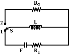
In the circuit shown, initially the switch is in position 1 for a long . Then the switch is shifted to position 2 for a long time. Find the total heat produced in $$R_2$$.
The peak voltage of an ac supply is $$300V$$. What is the rms voltage?
The frequency of applied ac emf applied to an ac circuit is quadrupled What is the effect on the (i) resistance (ii) inductive resistance and (iii) capacitive resistance.
An $$LCR$$ circuit has $$L=10\ mH, R=150\ \Omega$$ and $$C=1\ \mu F$$ connected in series to a source of $$150\sqrt{2} \cos \omega t$$ volt. At a frequency that is $$50\%$$ of the resonant frequency, calculate the average power (in $$watt$$) dissipated per cycle.
In the adjoining circuit, calculate the inductive reactance and the capacitive reactance. What should be the source frequency so that the two reactance become equal in magnitude? What would then be the impedance(in ohms) of the circuit?
When a coil is connected to a $$100\ V\ dc$$ supply. The current is $$2\ A$$. When the same coil is connected to a.c. source $$E=100\sqrt { 2 } \sin { \omega t }$$, the current is $$1\ A$$. Find the inductive reactance used :
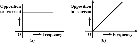
Draw the graphs showing variation of Inductive reactance and Capacitive reactance with frequency of applied A.C source.
A bulb and a capacitor are connected in series to a source of alternating current. If its frequency increases keeping the voltage constant, the bulb will
When a coil is connected to a $$100$$ $$V$$ DC supply, the current is $$2$$ $$A$$. When the same coil is connected to AC source $$E=100\sqrt{2}\sin\omega t$$, the current is $$1$$ $$A$$. Find the inductive reactance used in the circuit.
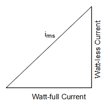
The r.m.s current in an ac circuit is $$1\ A$$. If the watt less current be $$\sqrt {3}A$$, Then what is the power factor
Given that,
rms current $${{i}_{rms}}=1\,A$$
Watt less current $${{i}_{w}}=\sqrt{3}\,A$$
Now, the watt full current
$$ {{i}_{f}}=\sqrt{{{\left( 1 \right)}^{2}}-{{\left( \sqrt{3} \right)}^{2}}} $$
$$ {{i}_{f}}=\sqrt{2} $$
Now, the power factor is
$$ P=\dfrac{{{i}_{f}}}{i_{rms}} $$
$$ P=\dfrac{\sqrt{2}}{1} $$
$$ P=\sqrt{2} $$
Hence, the power factor is $$\sqrt{2}$$
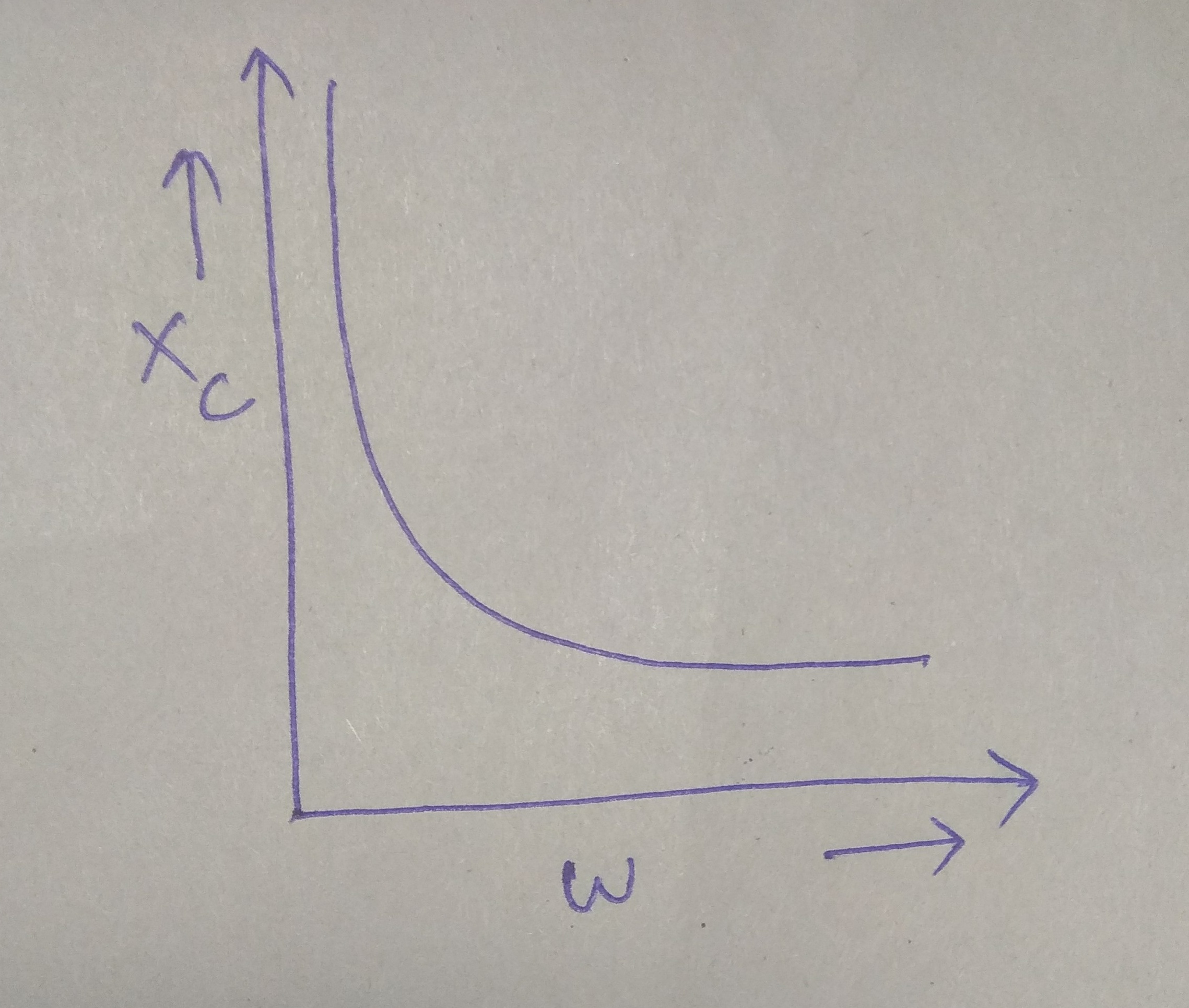
Plot a graph showing variation of capacitive reactance with the change in the frequency of the $$AC$$ source.
Capacitive reactance
$$ {{X}_{c}}=\dfrac{1}{2\pi
fC} $$
$$ f=\dfrac{1}{2\pi {{X}_{c}}C} $$
$$ {{X}_{c}}=Capacitive\,Reactance $$
$$ f=frequency $$
Graph between
capacitive reactance and change in frequency of AC source is shown in above
figure.
In the given circuit find out :
(i) maximum value of current in the circuit,
(ii) root mean square value of current in the circuit,

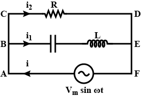
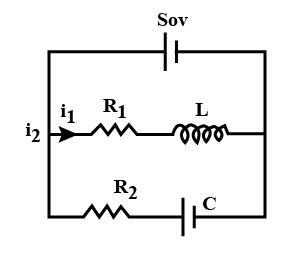
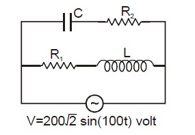
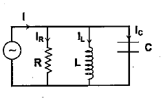
Consider the $$LCR$$ circuit shown in Fig. Find the net current $$i$$ and the phase of $$i$$. Show that $$i = \dfrac {V}{Z}$$. Find the impedance $$Z$$ for this circuit.
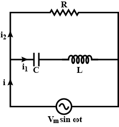
Potential across $$R =$$ Potential of source
$$P.D.$$ across $$R = V_{m}\sin \omega t$$
$$i_{2}R = V_{m}\sin \omega t$$
$$i_{2} = \dfrac {V_{m}\sin \omega t}{R} .... (I)$$
$$q_{1}$$ is charge on the capacitor at any time $$t$$, then for series combination of $$C, L$$ applying Kirchhoff's voltage law in loop $$ABEFA$$.
$$V_{C} + V_{L} = V_{M}\sin \omega t$$
$$\dfrac {q_{1}}{C} + L \dfrac {di_{1}}{dt} = V_{m}\sin \omega t$$
$$\dfrac {q_{1}}{C} + L \dfrac {d^{2}q_{1}}{dt^{2}} = V_{m}\sin \omega t .... II$$
Let $$q_{1} = q_{m} \sin (\omega t + \phi) .... III$$
$$i_{1} = \dfrac {dq_{1}}{dt} = q_{m}\omega \cos (\omega t + \phi) ...IV$$
$$\dfrac {d^{2}q_{1}}{dt^{2}} = -q_{m}\omega^{2} \sin (\omega t + \phi) ...V$$
Substitute the values of equations (III) and (V) in equation (II)
$$\dfrac {q_{m}\sin (\omega t + \phi)}{C} - Lq_{m}\omega^{2} \sin (\omega t + \phi) = V_{m}\sin \omega t$$
$$q_{m}\sin (\omega t + \phi) \left [\dfrac {1}{C} - L\omega^{2}\right ] = V_{m}\sin \omega t$$
at $$\phi = 0$$,
$$q_{m}\sin (\omega t + \phi) \left [\dfrac {1}{C} - L\omega^{2}\right ] = V_{m}\sin \omega t$$
$$q_{m}\left [\dfrac {1}{C} - L\omega^{2}\right ] \sin \omega t = V_{m}\sin \omega t$$
$$q_{m} \left [\dfrac {1}{C} - L\omega^{2}\right ] = V_{m}$$
$$q_{m} = \dfrac {V_{m}}{\omega \left [\dfrac {1}{C\omega - L\omega}\right ]} .... (VI)$$
Applying Kirchhoff's junction rule as junction $$B, i = i_{1} + i_{1}$$ using relation $$I, IV$$
$$i = \dfrac {V_{m}\sin \omega t}{R} + q_{m} \omega \cos (\omega t + \phi)$$
Now using relation VI for $$q_{m}$$ and at $$\phi = 0$$
$$i = \left [\dfrac {V_{m}\sin \omega t}{R} + \dfrac {V_{m}\omega \cos \omega t}{\omega \left [\dfrac {1}{\omega C} - \omega L\right ]}\right ]$$
$$i = \dfrac {V_{m}}{R}\sin \omega t + \dfrac {V_{m}}{\left (\dfrac {1}{\omega C} - \omega L\right )} \cos \omega t$$
Let
$$A = \dfrac {V_{m}}{r} = C\cos \phi .... (VII)$$
$$B = \dfrac {V_{m}}{\dfrac {1}{\omega C} - \omega L} = C \cos \phi .... (VIII)$$
$$i = C\cos \phi \sin \omega t + C \sin \phi . \cos \omega t$$
$$= C [\cos \phi \sin \omega t + \sin \phi \cos \omega t]$$
$$i = C \sin (\omega t + \phi)$$
Squaring and adding (VII), (VIII)
$$A^{2} + B^{2} = C^{2}\cos^{2}\phi + C^{2}\sin^{2} \phi$$
$$= C^{2}[\cos^{2} \phi + \sin^{2}\phi)$$
$$A^{2} + B^{2} = C^{2}$$
or $$C = \sqrt {A^{2} + B^{2}}$$
$$\phi = \tan^{-1} \dfrac {B}{A} = \tan^{-1} \dfrac {\dfrac {V_{m}}{\dfrac {1}{\omega C} - \omega L}}{\dfrac {V_{m}}{R}}$$
$$\therefore \tan \phi = \dfrac {R}{\left (\dfrac {1}{\omega C} - \omega L\right )}$$
$$\because C^{2} = A^{2} + B^{2} = \dfrac {V_{m}^{2}}{R^{2}} + \dfrac {V_{m}^{2}}{\left (\dfrac {1}{\omega C} - \omega L\right )^{2}}$$
$$C = \left [\dfrac {V_{m}^{2}}{R^{2}} + \dfrac {V_{m}^{2}}{\left (\dfrac {1}{\omega C} - \omega L\right )^{2}}\right ]^{\dfrac {1}{2}}$$
$$\therefore i = \left [\dfrac {V_{m}^{2}}{R^{2}} + \dfrac {V_{m}^{2}}{\left (\dfrac {1}{\omega C} - \omega L\right )^{2}}\right ]_{2} \sin (\omega t + \phi)$$
$$i = V_{m} \left [\dfrac {1}{R^{2}} + \dfrac {1}{\left (\dfrac {1}{\omega C} - \omega L\right )^{2}} \right ]^{\dfrac {1}{2}} \sin (\omega t + \phi) .... (IX)$$
And $$\phi = \tan^{-1} \dfrac {R}{\left (\dfrac {1}{\omega C} - \omega L\right )}$$
$$\because I = \dfrac {V}{R}$$ or $$i = \dfrac {V}{Z}$$
For ac $$i = \dfrac {V}{Z} \sin (\omega t + \phi) .... (X)$$
Comparing (IX) and (X)
So, $$\dfrac {1}{Z} = \left [\dfrac {1}{R^{2}} + \dfrac {1}{\left (\dfrac {1}{\omega C} - \omega L\right )^{2}}\right ]^{\dfrac {1}{2}}$$
This is the impedance $$Z$$ for the circuit.
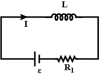
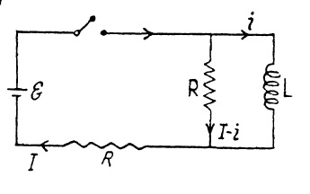
Find the time dependence of the current flowing through the inductance $$L$$ of the circuit shown in Fig. after the switch $$Sw$$ is shorted at the moment $$t = 0$$.
So, $$2L \dfrac {di}{dt} = \xi - Ri$$
This equation has the solution
$$i = \dfrac {\xi}{R} (1 - e^{-tR/ 2L})$$.
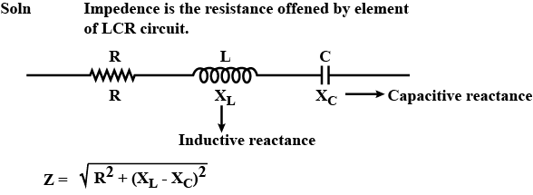
What is impedance?
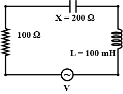
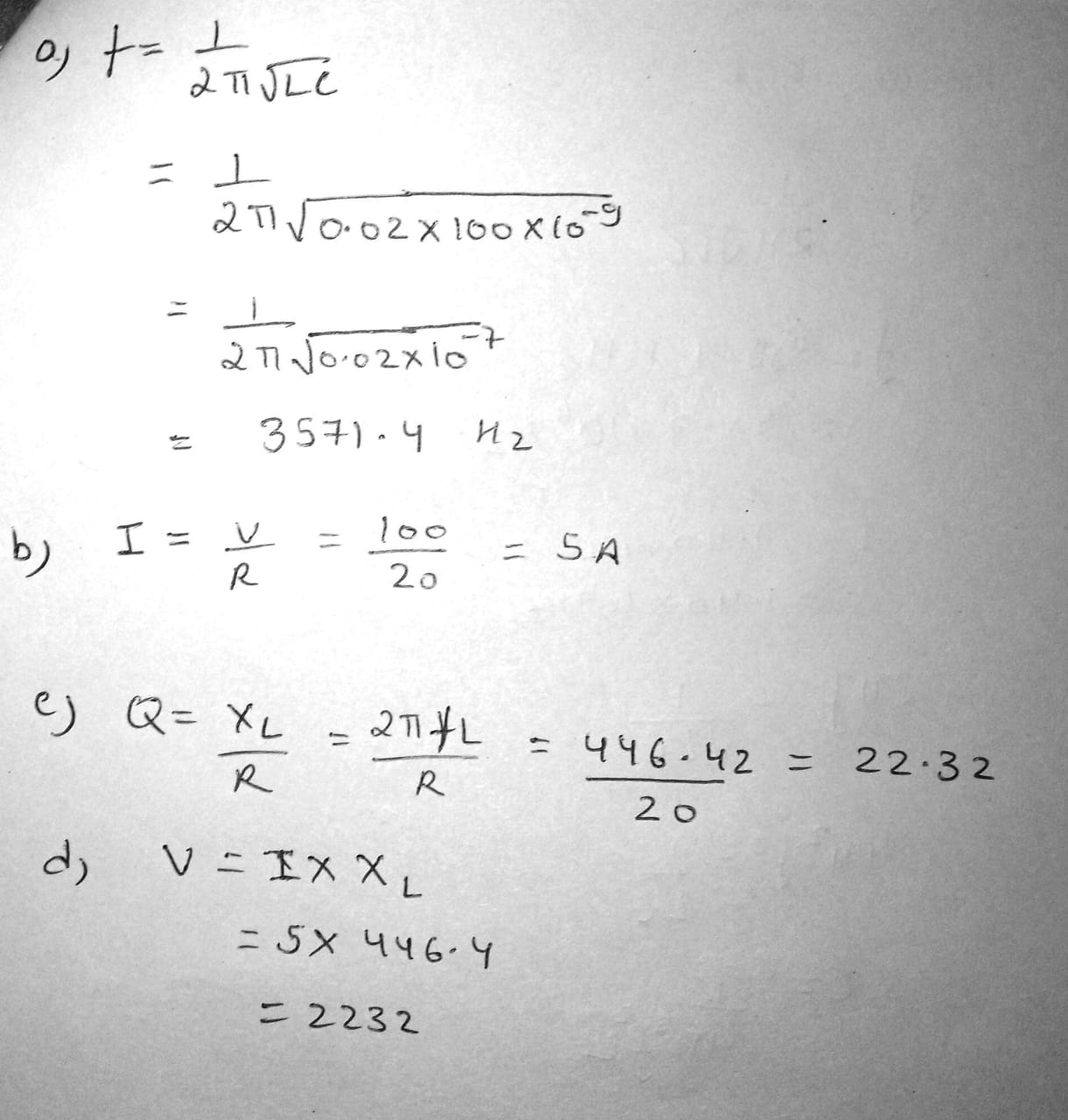
A circuit is set up by connecting inductance L=100mH resistor R=100$$\Omega $$ and a capacitor of reactance 200$$\Omega $$ in series An alternating emf of 150$$\sqrt{2}V,500m^{-1}$$ Hz is applied across this series combination. Calculate the power dissipated.
Define impedance. Arrive at the expression for impedance of a series LCR circuit using a phasor diagram.
An ac circuit consist of a series combination of circuit elements $$X$$ and $$Y$$. The Current is ahead of the voltage in phanse by $$\dfrac{\pi}{4}$$. If element $$X$$ is a pure resistor of $$100\Omega$$.
(a) name the circuit element $$Y$$.
(b) calculate the rms value of current, if rms value of voltage is $$141V$$.
(c) what will happen if the ac source is replaced by a dc source?
What is wattless current?
What are resonating frequency for two circuits.
Explain the term 'sharpness of resonance' in ac circuit.
The figure shows the graphical variation of the reactance of a capacitor with frequency of ac source.
An ideal inductor has the same reactance at $$100 Hz$$ frequency as the capacitor has at the same frequency. Find the value of inductance of the inductor.

A $$0.50 kg$$ body oscillates in SHM on a spring that, when extended $$2.0 mm$$ from its equilibrium position, has an $$8.0 N$$ restoring force. What are (a) the angular frequency of oscillation, (b) the period of oscillation and (c) the capacitance of an $$LC$$ circuit with the same period if $$L$$ is $$5.0 H$$?
To construct an oscillating $$LC$$ system, you can choose from a $$10 mH$$ inductor, a $$5.0\mu F$$ capacitor, and a $$2.0\mu F$$ capacitor. What are the (a) smallest, (b) second smallest, (c) second largest and (d) largest oscillation frequency that can be set up by these elements in various combinations?
The household supply of electricity is at 220 V (rms value) and 50 Hz. Find the peak voltage and the least possible time in which can change from the rms value to zero.
Find the time required for a 50 Hz alternating current to change its value from zero to the rms value.
In a certain oscillating $$LC$$ circuit, the total energy is converted from electrical energy in the capacitor to magnetic energy in the inductor in $$1.50\mu s$$. What are (a) the period of oscillation and (b) the frequency of oscillation? (c) How long after the magnetic energy is a maximum will it be a maximum again?
A variable capacitor with a range from $$10$$ to $$365 pF$$ is used with a coil to form a variable-frequency $$LC$$ circuit to tune the input to a radio. (a) What is the ratio of maximum frequency to minimum frequency that can be obtained with such a capacitor? If this circuit is to obtain frequencies from $$0.54MHz$$ to $$1.60 MHz$$, the ratio computed in (a) is too large. By adding a capacitor in parallel to the variable capacitor, this range can be adjusted. To obtain the desired frequency range, (b) what capacitance should be added and (c) what inductance should the coil have?
In the circuit shown in figure, the battery has negligible internal resistance. Show that the current in the circuit through the battery rises instantly to its steady state value $$E/R$$ when the switch is closed, provided that resistance R is $$\sqrt{L/C}$$
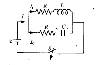
An inductor is connected across a capacitor whose capacitance can be varied by turning a knob. We wish to make the frequency of oscillation of this $$LC$$ circuit vary linearly with the angle of rotation of the knob, going from $$2*10^{5}$$ to $$4*10^{5}Hz$$ as the knob turns through $$180^{0}$$. If $$L=1.0 mH$$, plot the required capacitance $$C$$ as a function of the angle of rotation of the knob.
$$f=f_{0}\left ( 1+\dfrac{\theta }{180^{0}} \right )\Rightarrow \theta =180^{0}\left ( \dfrac{f}{f_{0}}-1 \right )$$.
where $$f_{0}=2*10^{5}Hz$$. Since $$f=\omega /2\pi =1/2\pi \sqrt{LC}$$, we are able to solve for C in terms of $$\theta$$:
$$C=\dfrac{1}{4\pi ^{2}Lf_{0}^{2}\left ( 1+\theta /180^{0} \right )^{2}}=\dfrac{81}{400000\pi ^{2}\left ( 180^{0}+\theta \right )^{2}}$$.
with SI units understood. After multiplying by $$10^{12}$$ (to convert to picofarads), this is plotted below:
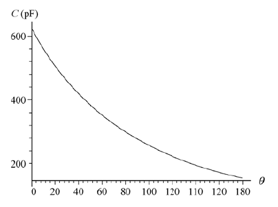
In an oscillating $$LC$$ circuit in which $$C=4.00 mF$$, the maximum potential difference across the capacitor during the oscillations is $$1.50V$$ and the maximum current through the inductor is $$50.0mA$$. What are (a) the inductance $$L$$ and (b) the frequency of the oscillations? (c) How much time is required for the charge on the capacitor to rise from zero to its maximum value?
$$L=\dfrac{1}{C}\left ( \dfrac{Q}{I} \right )^{2}=\dfrac{1}{C}\left ( \dfrac{CV_{max}}{I} \right )^{2}=C\left ( \dfrac{V_{max}}{I} \right )^{2}=\left ( 4.00*10^{-6}F \right )\left ( \dfrac{1.50V}{50.0*10^{-3}A} \right )^{2}=3.60\times10^{-3}H$$.
(b) Since $$f=\omega/2\pi$$, the frequency is,
$$f=\dfrac{1}{2\pi \sqrt{LC}}=\dfrac{1}{2\pi \sqrt{\left ( 3.60*10^{-3}H \right )\left ( 4.00*10^{-6}F \right )}}=1.33\times10^{3}Hz$$.
(c) Referring to figure below, we see that the required time is one-fourth of a period (where the period is the reciprocal of the frequency). Consequently,
$$t=\dfrac{1}{4}T=\dfrac{1}{4f}=\dfrac{1}{4\left ( 1.33*10^{3}Hz \right )}=1.88\times10^{-4}s$$.
An oscillating $$LC$$ circuit has an inductance of $$3.00 mH$$ and a capacitance of $$10.0\mu F$$. Calculate the (a) angular frequency and (b) period of the oscillation. (c) At time $$t=0$$, the capacitor is charged to $$200\mu C$$ and the current is zero. Describe the graph of charge on the capacitor as a function of time.
When under load and operating at an rms voltage of $$220V$$, a certain electric motor draws an rms current of $$3.00 A$$. It has a resistance of $$24.0\Omega$$ and no capacitive reactance. What is its inductive reactance?
(a) At what frequency would a $$6.0 mH$$ inductor and a $$10\mu F$$ capacitor have the same reactance? (b) What would the reactance be? (c) Show that this frequency would be the natural frequency of an oscillating circuit with the same $$L$$ and $$C$$.
An inductor $$200 mH$$, a capacitor $$100 \mu F$$ and a resistor $$10 \Omega$$ are connected in series to an a.c. source of $$100 V$$, having variable frequency. At what frequency of the applied voltage will the power factor of the circuit be $$1$$?
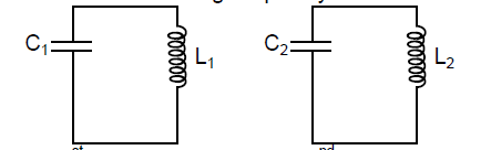
A series circuit containing inductance $$L_{1}$$ and capacitance $$C_{1}$$ oscillates at angular frequency $$\omega$$. A second series circuit, containing inductance $$L_{2}$$ and capacitance $$C_{2}$$, oscillates at the same angular frequency. In terms of $$\omega$$, what is the angular frequency of oscillation of a series circuit containing all four of these elements? Neglect resistance. (Hint: Use the formulas for equivalent capacitance and equivalent inductance).
A $$1.50\mu F$$ capacitor has a capacitive reactance of $$12.0\Omega$$. (a) What must be its operating frequency? (b) What will be the capacitive reactance if the frequency is doubled?
A generator with an adjustable frequency of oscillation is wired in series to an inductor of $$L=2.50 mH$$ and a capacitor of $$C=3.00\mu F$$. At what frequency does the generator produce the largest possible current amplitude in the circuit?
A coil of inductance $$88 mH$$ and unknown resistance and a $$0.94\mu F$$ capacitor are connected in series with an alternating emf of frequency $$930 Hz$$. If the phase constant between the applied voltage and the current is $$75$$, what is the resistance of the coil?
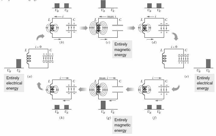
In above figure, $$R=14.0\Omega$$, $$C=6.20\mu F$$, and $$L=54.0 mH$$, and the ideal battery has emf $$\xi=34.0V$$. The switch is kept at a for a long time and then thrown to position $$b$$. What are the (a) frequency and (b) current amplitude of the resulting oscillations?
Sketch a graph showing variation of reactance of a capacitor with frequency in an AC circuit.
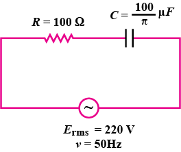
A resistor of $$100 \Omega$$ and a capacitor of $$100/\pi\ \mu F$$ are connected in series to a $$220 V$$, $$50 Hz$$ a.c. supply. Calculate the current in the circuit. Calculate the (rms) voltage across the resistor and the capacitor. Do you find the algebraic sum of these voltages more than the source voltage? If yes, how do you resolve the paradox?
The figure shows a series $$LCR$$ circuit with $$L=5.0H$$, $$C=80 \mu F$$, $$R=40 \Omega$$ connected to a variable frequency $$240V$$ source. Calculate the angular frequency of the source which drives the circuit at resonance.
Prove that the power dissipated in an ideal resistor connected to an ac source is $$\dfrac{{V_{eff}}^{2}}{R}$$.
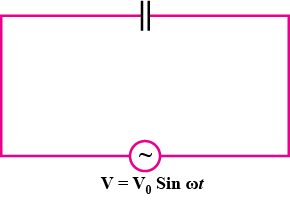
Show that the current leads the voltage in phase by $$\pi/2$$ in an ac circuit containing an ideal capacitor.
A capacitor of unknown capacitance, a resistor of $$100 \Omega$$ and an inductor of self-inductance $$L= (\dfrac{4}{\pi^{2}})$$ henry are connected in series to an ac source of $$200 V$$ and $$50 Hz$$. Calculate the value of the capacitance and impedance of the circuit when the current is in phase with the voltage.
In a series $$LCR$$ circuit, obtain the conditions under which the impedance of the circuit is minimum,
A capacitor of unknown capacitance is connected across a battery of V volts. The charge stored in it is $$360 \mu C$$. when potential across the capacitor is reduced by $$120 V$$, the charge stored in it becomes $$120 \mu C$$.
The potential V and the unknown capacitance C.
When a circuit element $$X$$ is connected across an a.c. source, a current of $$\sqrt{2} A$$ flows through it and this current is in phase with the applied voltage. When another element $$Y$$ is connected across the same a.c. source, the same current flows in the circuit but it leads the voltage by $$\dfrac{\pi}{2}$$ radians. Find the net impedance.
Calculate the wattless current of the given ac circuit.
$$\text{Wattless Current, } I_{wattless} = Isin \varphi = I(\dfrac{X_{C}}{Z}) = 2 \times \dfrac{20}{25}A = 1.6A$$
The instantaneous voltage from an ac source is given by $$E=300 sin 314t$$; what is the rms voltage of the source?
What is the power dissipated in an ac circuit in which voltage and current are given by $$V = 230sin (\omega t +\dfrac{\pi}{2}) \text{ and } I = 10sin\omega t$$?
The instantaneous current in an ac circuit is $$i=0.5sin314t$$, what is the frequency of the current?
Derive an expression for impedance of an a.c. circuit consisting of an inductor and a resistor.
An ac voltage $$V = V_{0} sin \omega t$$ is applied across a pure inductor of inductance $$L$$. Draw graphs of V and i versus $$\omega t$$ for the circuit.
A $$2 \mu F$$ capacitor, $$100 W$$ resistor and $$8 H$$ inductor are connected in series with an AC source.
What should be the frequency of the source such that current drawn in the circuit is maximum? What is this frequency called?
Explain why the reactance provided by a capacitor to an alternating current decreases with increasing frequency.
Explain the term inductive reactance.
Define the term Sharpness of Resonance. Under what condition, does a circuit become more selective?
Explain why the reactance offered by an inductor increases with increasing frequency of an alternating voltage.
State the condition for resonance to occur in series $$LCR$$ a.c. circuit and derive an expression for resonant frequency.
Define the term capacitive reactance.
A device $$X$$ is connected to an ac source $$V =V_{0}sin \omega t$$. The variation of voltage, current and power in one cycle is shown in the graph (see figure). Identify the device $$X$$.
A coil of $$0.01$$ henry inductance and $$1\ ohm$$ resistance is connected to $$200\ volt, 50\ Hz$$ ac supply. Find the impedance of the circuit and time lag between maximum alternating voltage and current.
A series $$LCR$$ circuit is connected to an ac source having voltage $$V=V_{0} sin \omega t$$. Derive the expression for resonant frequency.
A series $$LCR$$ circuit is connected to an ac source having voltage $$V=V_{0} sin \omega t $$. Derive the expression for the impedance.
When all the three elements are connected in series across the same source, determine the impedance of the circuit.
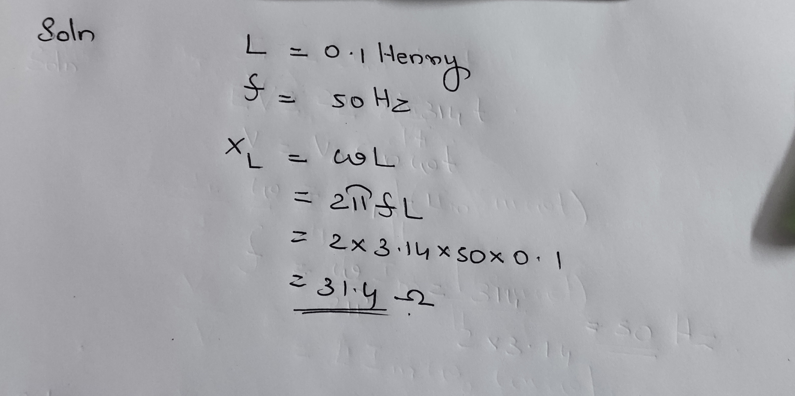
The inductance of a coil is $$0.1H$$. It is connected to an alternating current of $$50Hz$$ frequency. Find out the reactance.
Answer in brief:
For a very high frequency AC supply, a capacitor behaves like a pure conductor.Why?
At which time, sinusoidal alternating current will be
(i) $$\cfrac{1}{2}$$ time
(ii) $$\cfrac { \sqrt { 3 } }{ 2 } $$ time of its peak value
The inductance of the coil is $$1H$$
(i) At which frequency will its reactance be $$3140\Omega$$
(ii) What will be the capacity of the capacitor so that its reactance remain same at the same frequency?
An alternating source of $${V}_{rms}=120V,f=60Hz$$ is connected to an series circuit containing $$L=200mH$$, $$C=40\mu F$$, $$R=20\Omega$$. Determine
(i) total reactance
(ii) impedance
(iii) power factor
(iv) average power
A series LCR circuit connected through an alternating voltage $$230V$$. If $$L=5H,C=80\mu F, R=40\Omega$$, then find out the:
(i) resonant frequency
(ii) impedance of the circuit and peak value of current at resonant frequency
(iii) square mean root value of voltages at three components.
A consider of $$120\mu F$$ is connected through an ac source of frequency $$50Hz$$. Calculate its capacitive reactance. If frequency changes to $$5MHz$$, then what will be the effect on reactance?
The ohmic resistance of a coil is $$6\Omega$$. If impedance of the coil is $$10\Omega$$, then find inductive reactance $$\left( { X }_{ L } \right) $$ of the coil.
Write value of wattless current in an ac circuit.
Anwser in brief.
What is wattles current?
An inductance, a capacitance and a resistance are in series. If $$L=0.1H,C=20\mu F, R=10\Omega$$, then at which frequency, the circuit will be in resonance?
A circuit consist of a capacitor with capacitance $$C$$ and a coil with active resistance $$R$$ and inductance $$L$$ connected in parallel. Find the impedance of the circuit at frequency $$\omega$$ of alternating voltage.
A cell of emf $$50 V$$, with negligible resistance is connected in parallel through a switch $$S$$ to two branches: one is R-L branch and other is R-C branch as shown in the figure. Now in Column I, certain numerical values are given as A, B, C and D, which may correspond to one or more physical quantities, given in Column II.
$$[R_{1}=25\Omega ,R_{2}=5\Omega ,L=10H,C=20\mu F]$$. Use $$e^{x}\simeq 1+x,x< < 1$$.

A series LRC circuit is activated by a sinusoidal ac volage e = E$$_{o}$$ sin $$\omega $$t, with varying frequency $$\omega $$. In Column I, different frequency values are given and in Column II, different responses of the circuit are shown. One or more of items in Column II may match with any of the frequencies given in Column I. $$[ \omega _{o}=\frac{1}{\sqrt{LC}}]$$
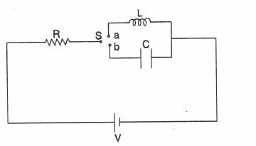
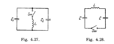
In the circuit shown aside the switch $$S$$ can be moved from $$a$$ to $$b,$$ connecting either inductance $$L$$ or capacitance $$C$$ to a resistor $$R$$.when the key is pressed the switch $$S$$ will be at either $$a$$ or $$b$$.In column $$I,$$ the variation of physical quantities charge,current,voltage etc.in time are given in terms of constants $$C's$$ and $$K's$$ the values of which depends on emf $$V,R,L$$ and $$C$$.In column $$II,$$ the physical quantities under different switch positions are given. the variation in column $$I$$ may correspond to one or more quantities of Column $$II$$.
In the shown circuit, $$R_{1}=10\Omega ,L=\dfrac{\sqrt{3}}{10}H,R_{2}=20\Omega,C=\dfrac{\sqrt{3}}{2}\ milli-farad$$ and $$t$$ is time in seconds. Then at the instant current through $$R_1 is 10\sqrt2\ A$$ ;find the current through resistor $$R_2$$ in amperes.
If the the current amplitude is $$\dfrac {x}{1000}A$$, find the value of $$x$$.
What are the values of the elements?
Derive an expression for the circuit current.
A coil of inductance 0.50 H and resistance $$100 \Omega$$ is connected to a 240 V, 50 Hz ac supply.(a) What is the maximum current in the coil?(b) What is the time lag between the voltage
maximum and the current maximum?
(b) What is the time lag between the voltage maximum and the current maximum?
In a series LCR circuit connected to an a.c. source of voltage $$v = v_m sin \omega t$$, use phasor diagram to derive an expression for the current in the circuit. Hence, obtain the expression for the power dissipated in the circuit. Show that power dissipated at resonance is maximum.
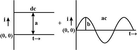
If a direct current of value $$A$$ ampere is superimposed on an alternating current $$I = b \sin \omega t$$ flowing through a wire, what is the effective (rms) value of the resulting current in the circuit?
A choke coil is needed to operate an arc lamp at $$160V$$ (rms) and $$50Hz$$. The arc lamp has an effective resistance of $$5\Omega$$ when running at $$10A$$ (rms). Calculate the inductance of the choke coil. If the same arc lamp is to be operated on $$160V$$ DC, what additional resistance would be required. Compare the power losses in both the cases.
For resistance R and capacitance C in series, the impedance is twice that of a parallel combination of the same elements. What is the frequency of applied emf?
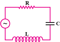
For the circuit shown in the figure. Find the expressions for the impedance of the circuit and phase of current:
Obtain the relation $$I = I_0 \sin ( \omega t + \pi / 2 ) $$ and $$X_C = 1 / \omega C $$ for a pure capacitor across which an altering $$emf= V = V_0 \sin \omega t $$ is applied. Draw a phasor diagram showing $$emf V$$ , current $$I$$ and their phase difference $$ \phi $$
The phase difference between the current and voltage is $$90^\circ $$.
It can be shown in the above phasor diagram,
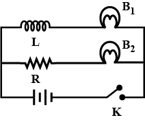
In the given circuit, the value of resistance effect of the coil L is exactly equal to the resistance R. Bulbs B1 and B2 are exactly identical. Answer the following question.
a) Which one of the two bulbs lights up earlier, when key k is closed and why?
b) What will be the comparative brightness of the two bulbs after sometime if the key K is kept closed and why?
A resistance of $$ 20 \Omega $$ is connected to a source of alternating current rated $$110 V , 50 Hz$$ Find the $$rms$$ current.
Calculate the impedance of the circuit.
An inductance of $$2.0$$ H,a capacitance of $$18$$ and a resistance of $$10$$ are connected to an AC source of $$20$$ with adjustable frequency (a) What frequency should be chosen to maximum the current (RMS) in the circuit? (b) What is the value of this maximum current (RMS)?
Obtain an expression for impedance of resistor, pure inductor and capacitor connected in series across alternating $$e.m.f$$. State formula for phase difference.
In a Zener regulated power supply a Zener diode with $$V_z=6.0V$$ is used for regulation. The load current is to be $$4.0mA$$ and the unregulated input is $$10.0V$$. What should be the value of series resistor $$R_s$$
The effective resistance in between the points A and B in the circuit given is?
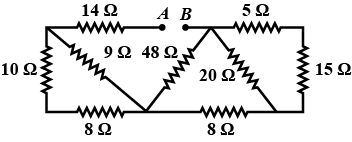
When does LCR series circuit has minimum impedance.
In a series LCR circuit with an AC source, $$R=300\ \Omega,\ C=20\ \mu F,\ L=10\ henry\ \epsilon _{max}=50\ V$$ and $$v=50/\pi\ Hz$$. Find
(a) the $$rms$$ current in the circuit.
(b) the $$rms$$ potential differences across the capacitor, the resistor and the inductor, Note that the sum of the $$rms$$ potential difference across the three elements is greater than the $$rms$$ voltage of the source.
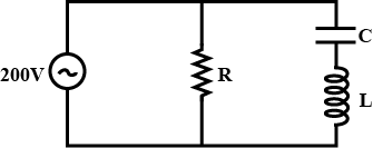
Assuming expression for impedance in a parallel resonant circuit, state the condition for parallel resonance. Define resonant frequency and obtain and expression for it.
Admittare $$\gamma=\gamma_R+\gamma_c+\gamma_2$$
$$=\dfrac{1}{R}+jcw+\dfrac{1}{jLw}$$
Resonance occurs when the current and voltage are in phase. To achieve this ,the imaginary past of admittance (or importance) must be zero
$$\therefore jcw+\dfrac{1}{jLw}=0,w=\dfrac{1}{\sqrt{Lc}}=2\pi f_R$$.
Resonant frequency the frequency at which the voltage and current are in phase in the circuit
We know $$w=\dfrac{1}{\sqrt{Lc}}=2\pi f_{R1}$$ $$\therefore =\dfrac{1}{2 \pi \sqrt{Lc}}$$
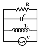
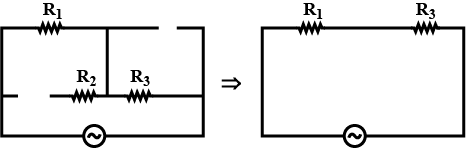
Draw the effective equivalent circuit of the circuit shown in Fig., at very high frequencies and find the effective impedance.
In similar way, $$X_{C} = \dfrac {1}{2\pi vC}$$
At high frequency, $$X_{C}$$ will be low.
So reactance of capacitance can be considered negligible and capacitor can be considered as short circuited.
Here the above figure is equivalent circuit to given circuit.
Total impedance, $$Z = R_{1} + R_{3}$$.
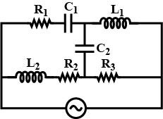
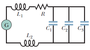
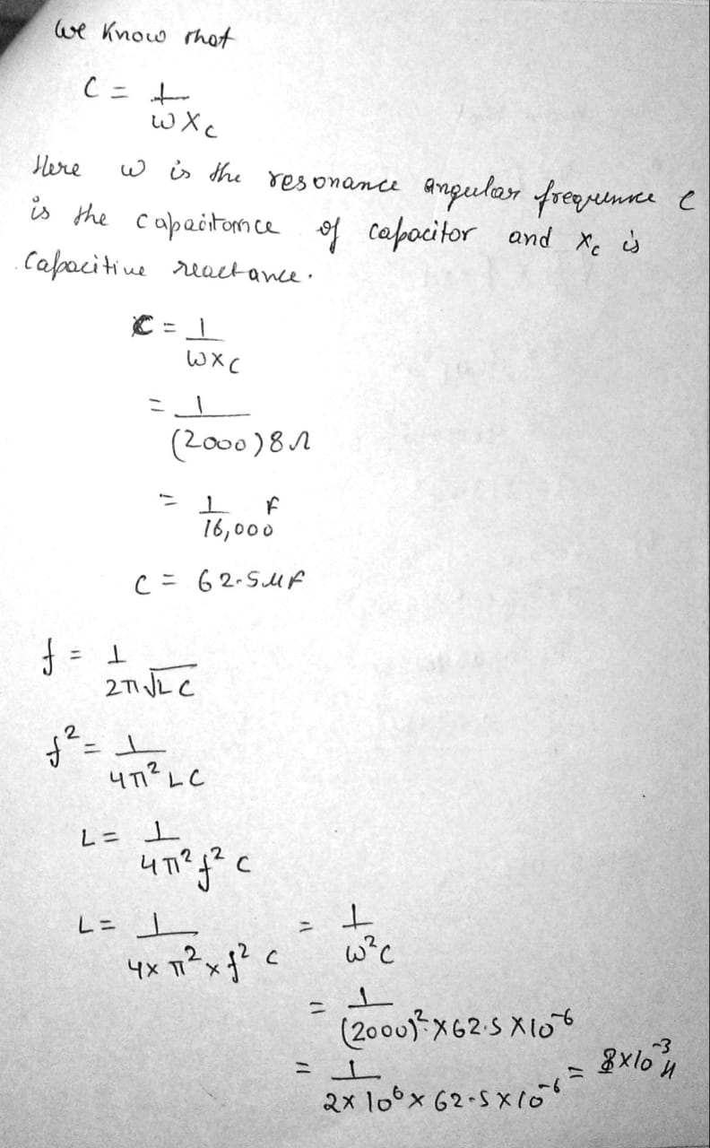
In above figure, a generator with an adjustable frequency of oscillation is connected to resistance $$R=100\Omega$$, inductances $$L_{1}=1.70mH$$ and $$L_{2}=2.30mH$$, and capacitances $$C_{1}=4.00\mu F$$, $$C_{2}=2.50\mu F$$, and $$C_{3}=3.50\mu F$$. (a) What is the resonant frequency of the circuit? What happens to the resonant frequency if (b) $$R$$ is increased, (c) $$L_{1}$$ is increased and (d) $$C_{3}$$ is removed from the circuit.
For a certain driven series $$RLC$$ circuit, the maximum generator emf is $$125 V$$ and the maximum current is $$3.20 A$$. If the current leads the generator emf by $$0.982 rad$$, what are the (a) impedance and (b) resistance of the circuit? (c) Is the circuit predominantly capacitive or inductive?
A series circuit with resistorinductorcapacitor combination $$R_{1},L_{1},C_{1}$$ has the same resonant frequency as a second circuit with a different combination $$R_{2},L_{2},C_{2}$$. You now connect the two combinations in series. Show that this new circuit has the same resonant frequency as the separate circuits.
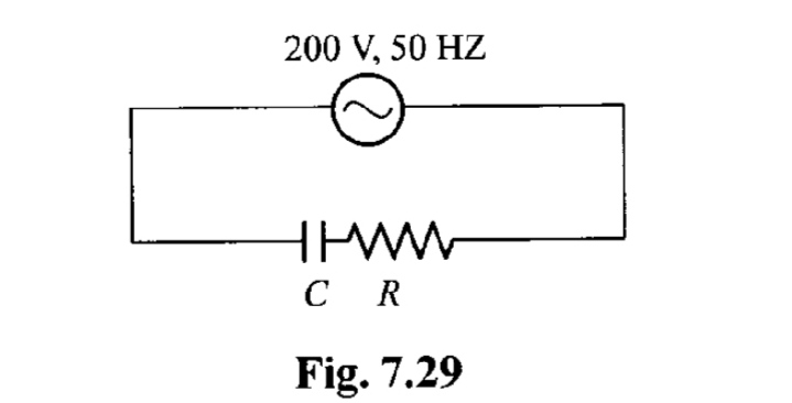
In an RC series circuit ( see Fig. 7.29 ) , the rms voltage of source is $$ 200 \,V $$ and its frequency is $$ 50 \,Hz $$ . If $$ R = 100 \Omega $$ and $$ C $$ =$$ \dfrac{100}{\pi} \mu F $$ , find
(i) Impedance of the circuit ,
(ii) Power factor angle ,
(iii) Power factor ,
(iv) Current ,
(v) Maximum current ,
(vi) Voltage across R ,
(vii) Voltage across C ,
(viii) Maximum voltage across R ,
(ix) Maximum voltage across C ,
(x) $$ < P > $$ ,
(xi) $$ < P_R > $$ ,
(xii) $$ < P_C > $$
(xiii) $$ i(t) , V_R (t) $$ and $$ V_C(t) $$
A $$45.0mH$$ inductor has a reactance of $$1.30k\Omega$$. (a) What is its operating frequency? (b) What is the capacitance of a capacitor with the same reactance at that frequency? If the frequency is doubled, what is the new reactance of (c) the inductor and (d) the capacitor?
The resonance frequency.
In a series oscillating $$RLC$$ circuit, $$R=16.0\Omega$$, $$C=31.2\mu F$$, $$L=9.20 mH$$ and $$\xi _{m}=\xi _{m}\sin \omega _{d}t$$ with $$\xi _{m}=45.0V$$ and $$\omega _{d}=3000rad/s$$. For time $$t=0.442 ms$$ find (a) the rate $$P_{g}$$ at which energy is being supplied by the generator, (b) the rate $$P_{c}$$ at which the energy in the capacitor is changing, (c) the rate $$P_{L}$$ at which the energy in the inductor is changing and (d) the rate $$P_{R}$$ at which energy is being dissipated in the resistor. (e) Is the sum of $$P_{C}$$, $$P_{L}$$ and $$P_{R}$$ greater than, less than or equal to $$P_{g}$$?
An air conditioner connected to a $$120 V$$ $$(rms)$$ $$AC$$ line is equivalent to a $$12.0\Omega$$ resistance and a $$1.30\Omega$$ inductive reactance in series. Calculate (a) the impedance of the air conditioner and (b) the average rate at which energy is supplied to the appliance.
What will be value of impedence, frequency and power factor for a resonant LCR circuit? Write the expression
What will be the effect on inductive reactance and capacitive reactance on the increasing frequency of the alternating current?
The natural oscillation frequency.
What inductance must be connected to a $$17 pF$$ capacitor in an oscillator capable of generating $$550 nm$$ (i.e.,visible) electromagnetic waves? Comment on your answer.
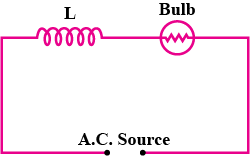
An inductor $$L$$ of reactance $$X_{L}$$ is connected in series with a bulb $$B$$ to an ac source as shown in figure. Explain briefly how does the brightness of the bulb change when a capacitor of reactance $$X_{C} = X_{L}$$ is included in the circuit.
What will be impedance in a series LCR circuit?
A source of sinusoidal emf with constant voltage is connected in series with an oscillating circuit with quality factor $$Q=100$$. At a certain frequency of the external voltage the heat power generated in the circuit reaches the maximum value. How much (in per cent) should this frequency be shifted to decrease the power generated $$n=2.0$$ times?
Conceptual Questions(7)
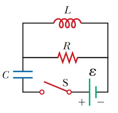
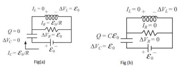
The open switch in Figure is thrown closed at $$t =0$$. Before the switch is closed, the capacitor is uncharged and all currents are zero. Determine the currents in $$L, \,C$$, and $$R$$, the emf across $$L$$, and the potential differences across $$C$$ and $$R$$
(a) at the instant after the switch is closed and
(b) long after it is closed.
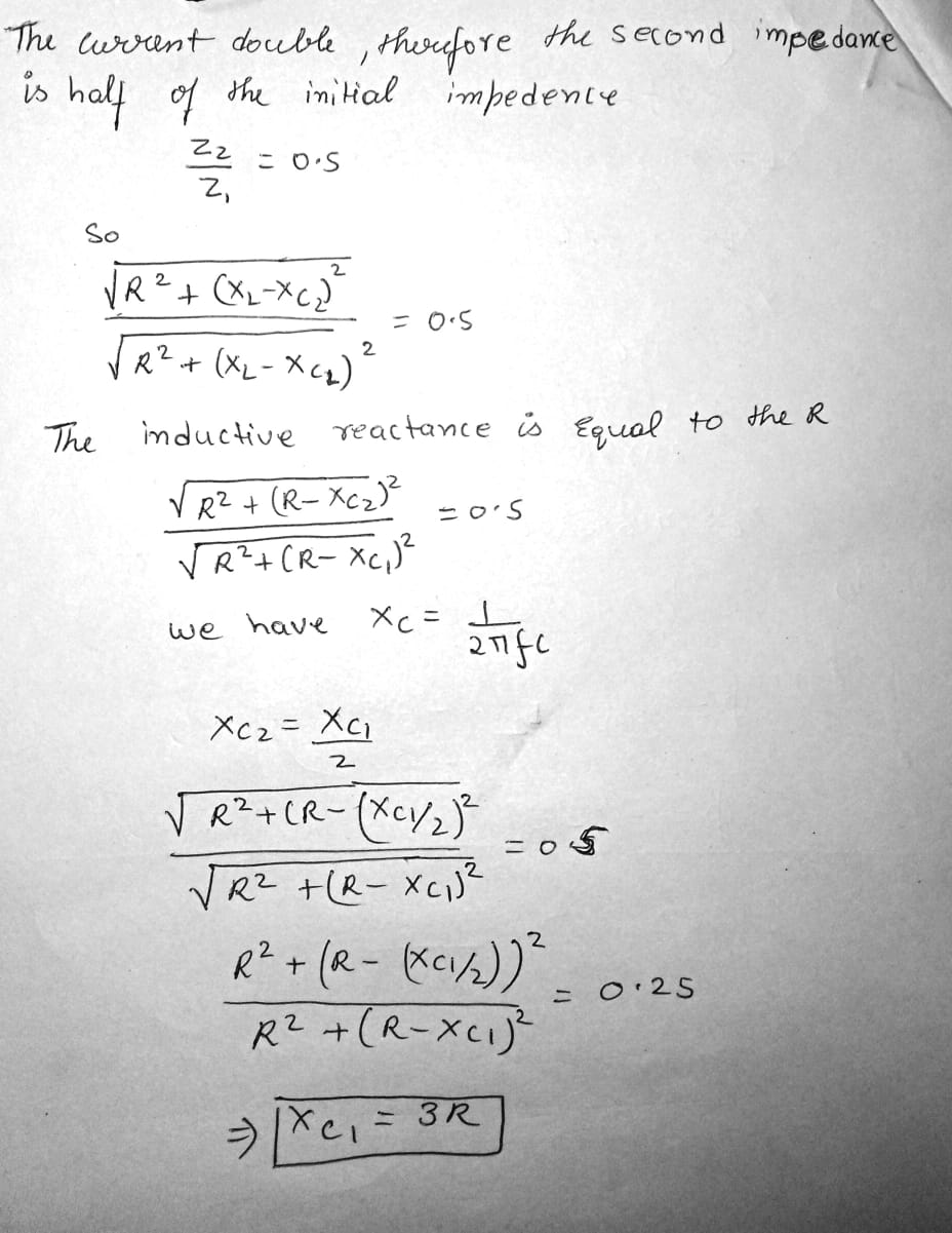
In an RLC series circuit that includes a source of alternating current operating at fixed frequency and voltage, the resistance $$R$$ is equal to the inductive reactance. If the plate separation of the parallel-plate capacitor is reduced to one-half its original value, the current in the circuit doubles. Find the initial capacitive reactance in terms of $$R$$.
What mean power should be fed to an oscillating circuit with active resistance $$R=0.44\Omega$$ to maintain undamped harmonic oscillations with current amplitude $$I_m=30mA$$?
Oscillations in an LC Circuit(53)
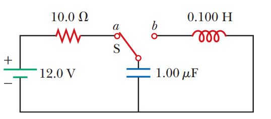
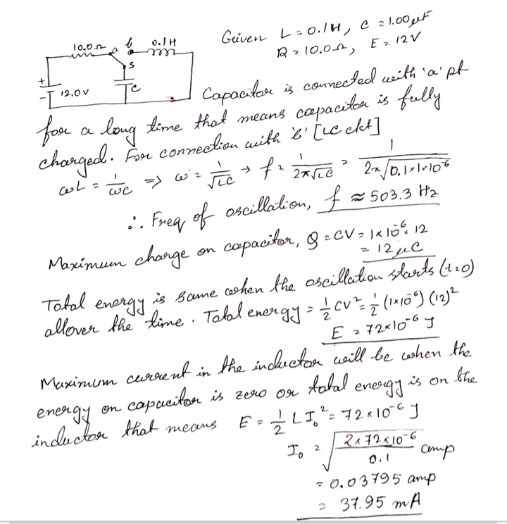
The switch in Figure is connected to position a for a long time interval. At $$t = 0$$, the switch is thrown to position "b". After this time, what are (a) the frequency of oscillation of the LC circuit, (b) the maximum charge that appears on the capacitor, (c) the maximum current in the inductor, and (d) the total energy the circuit possesses at $$t = 3.00 \,s$$?
The RLC Circuit(58)
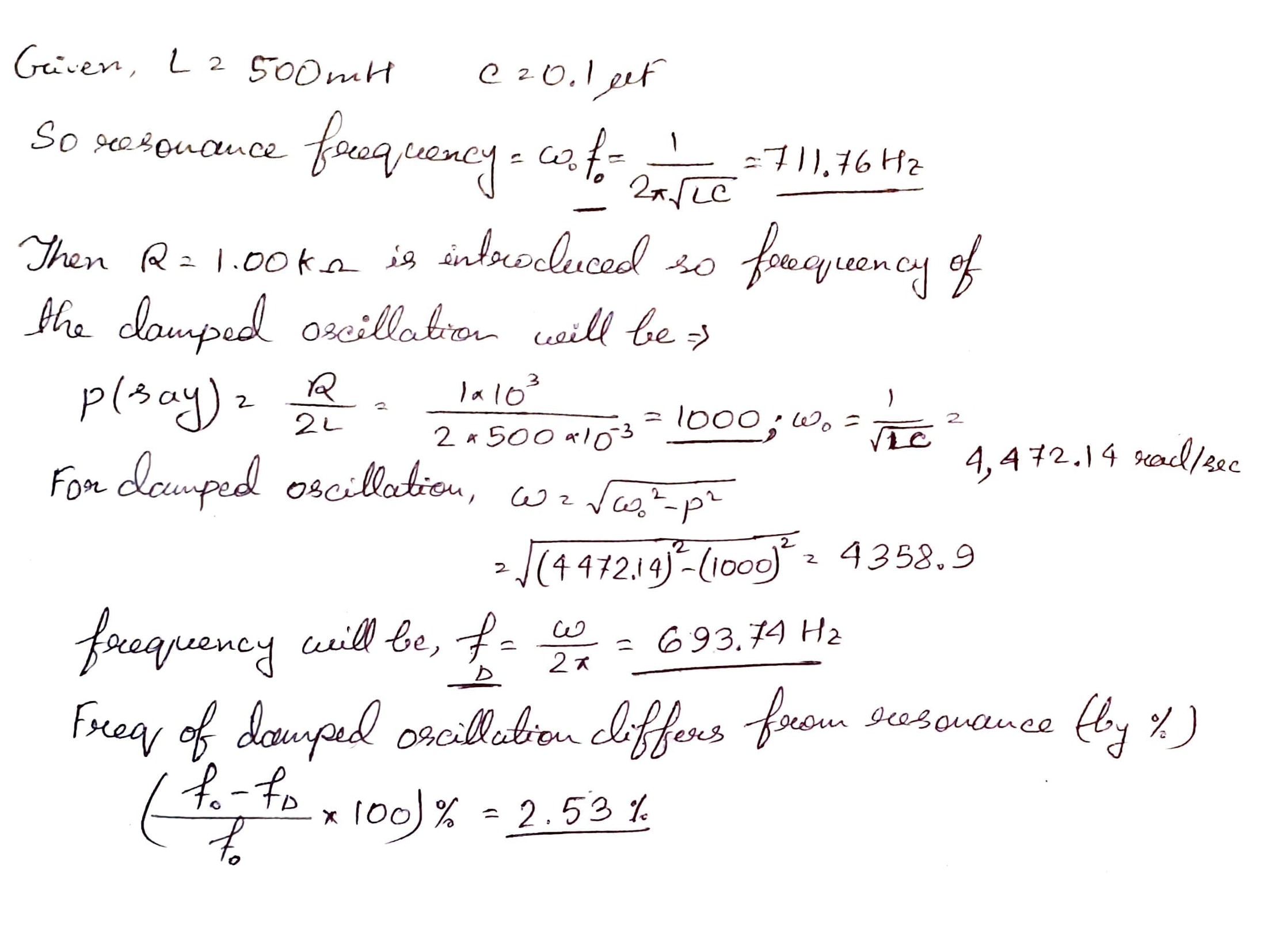
Consider an LC circuit in which $$L = 500 \,mH$$ and $$C = 0.100 \mu F$$. (a) What is the resonance frequency $$\omega_0$$?(b) If a resistance of $$1.00 k\Omega$$ is introduced into this circuit, what is the frequency of the damped oscillations? (c) By what percentage does the frequency of the damped oscillations differ from the resonance frequency?
An oscillating circuit consist of capacitance $$C=10\mu F$$, inductance $$L=25mH$$, and active resistance $$R=1.0\Omega$$. How many oscillation frequency period does it take for the current amplitude to decrease $$\theta -$$ fold?
A loop Fig is formed by two parallel conductors connected by a solenoid with inductance $$L$$ and a conducting rod of mass $$m$$ which can freely (without friction) slide over the conductors. The conductors are located in a horizontal plane in a uniform vertical magnetic field with induction $$B$$. The distance between the conductors is equal to $$l$$. At the moment $$t=0$$ the rod imparted an initial velocity $$\nu_0$$ directed to the right. Find the law of its motion $$x(t)$$ if the electric resistance of the loop is negligible.
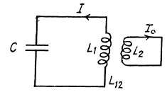
An oscillating circuit consist of a capacitor of capacitance $$C$$ and a solenoid with inductance $$L_1$$. The solenoid is inductively connected with a short-circuited coil having an inductance $$L_2$$ and a negligible active resistance. Their mutual inductance coefficient is equal to $$L_{12}$$. find the natural frequency of the given oscillating circuit.
$$L_2\dfrac{dI_2}{dt}=-L_{12}\dfrac{dI_2}{dt}$$
from the second equation
$$L_2I_2=-L_{12}I_1$$
Then
$$\left(L_1-\dfrac{L_{12}^2}{L_2}\right)\ddot {I}+\dfrac{I_1}{C}=0$$
Thus the current oscillates with frequency
$$\omega =\dfrac{1}{\sqrt{\left(L_1-\dfrac{L_{12}^2}{L_2}\right)}}$$
Additional Problems(64)
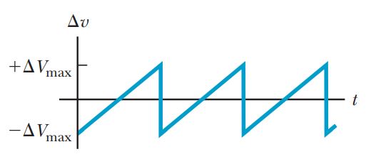
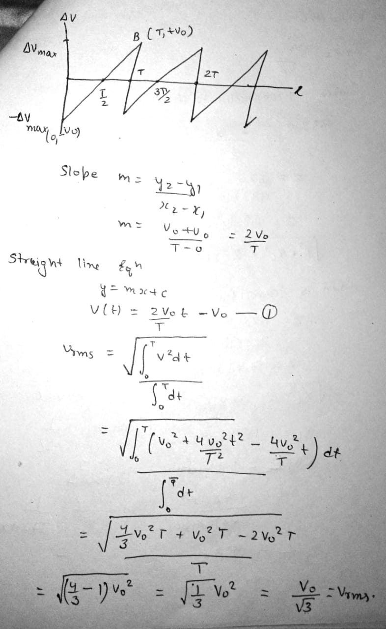
Show that the rms value for the sawtooth voltage shown in Figure is $$\Delta V_{max}/\sqrt{3}$$.
Additional Problems(68)
A series RLC circuit has resonance angular frequency $$2.00 \times 10^3 \,rad/s$$. When it is operating at some input frequency, $$X_L = 12.0 \Omega$$ and $$X_C = 8.00 \Omega$$. (a) Is this input frequency higher than, lower than, or the same as the resonance frequency? Explain how you can tell.(b) Explain whether it is possible to determine the values of both L and C. (c) If it is possible, find L and C.If it is not possible, give a compact expression for the condition that L and C must satisfy.
Additional Problems(63)
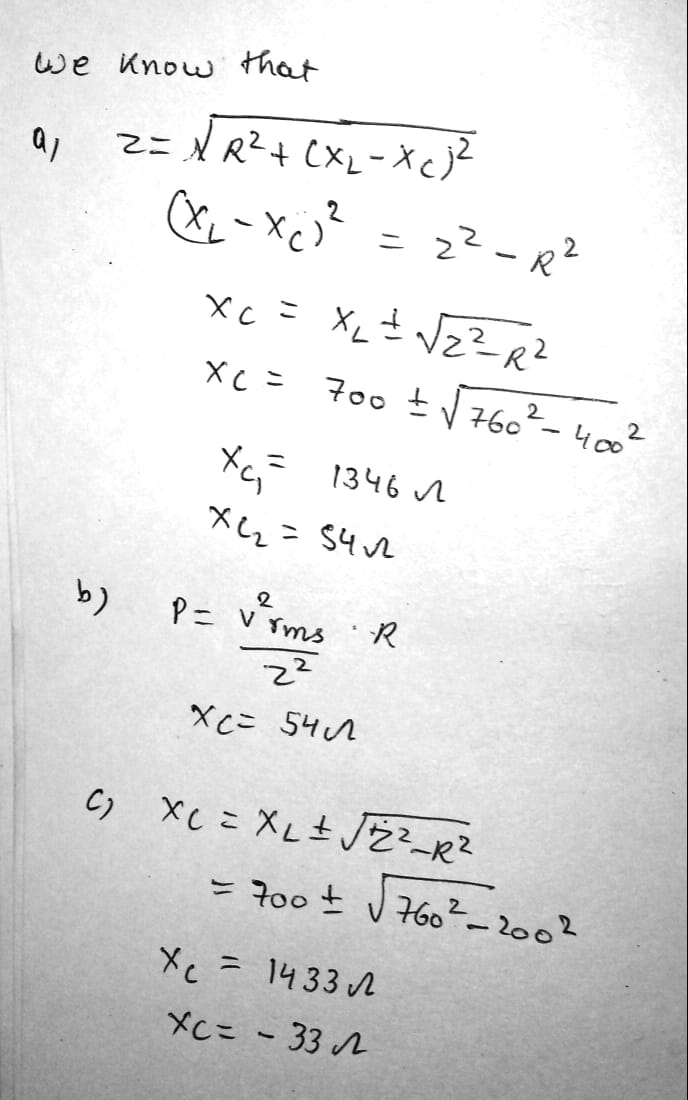
A $$400-\Omega$$ resistor, an inductor, and a capacitor are in series with an AC source. The reactance of the inductor is $$700 \,\Omega$$, and the circuit impedance is $$760 \,\Omega$$. (a) What are the possible values of the reactance of the capacitor? (b) If you find that the power delivered to the circuit decreases as you raise the frequency, what is the capacitive reactance in the original circuit? (c) Repeat part (a) assuming the resistance is $$200 \,\Omega$$ instead of $$400 \,\Omega$$ and the circuit impedance continues to be $$760 \,\Omega$$.
Resonance in a Series RLC Circuit(42)
A series RLC circuit has components with the following values: $$L = 20.0 \,mH, \,C = 100 \,nF, \,R = 20.0 \,\Omega$$, and $$\Delta V_{max} = 100 \,V$$, with $$\Delta v = \Delta V_{max} \sin \omega t$$. Find (a) the resonant frequency of the circuit, (b) the amplitude of the current at the resonant frequency, (c) the Q of the circuit, and (d) the amplitude of the voltage across the inductor at resonance.
An AC voltage of the form $$\Delta v = 90.0 \sin \,350 t$$, where $$\Delta v$$ is in volts and $$t$$ is in seconds, is applied to a series RLC circuit. If $$R = 50.0 \,\Omega, \,C = 25.0 \mu F$$, and $$L = 0.200 \,H$$, find (a) the impedance of the circuit, (b) the rms current in the circuit, and (c) the average power delivered to the circuit.
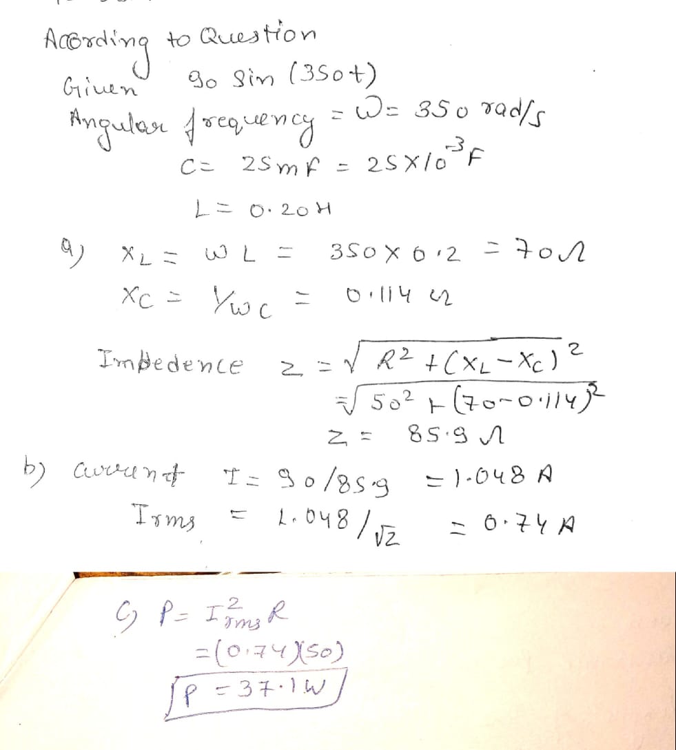
Power in an AC Circuit(41)
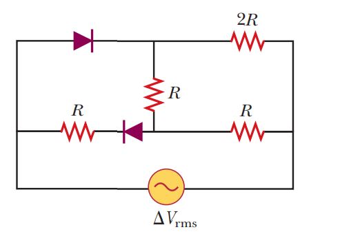
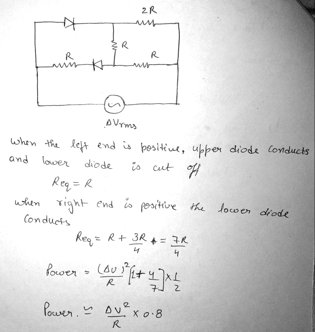
A diode is a device that allows current to be carried in only one direction (the direction indicated by the arrowhead in its circuit symbol). Find the average power delivered to the diode circuit of Figure in terms of $$\Delta V_{rms}$$ and $$R$$.
Class 12 Medical Physics Extra Questions
- Alternating Current Extra Questions
- Atoms Extra Questions
- Current Electricity Extra Questions
- Dual Nature Of Radiation And Matter Extra Questions
- Electric Charges And Fields Extra Questions
- Electromagnetic Induction Extra Questions
- Electromagnetic Waves Extra Questions
- Electrostatic Potential And Capacitance Extra Questions
- Magnetism And Matter Extra Questions
- Moving Charges And Magnetism Extra Questions
- Nuclei Extra Questions
- Ray Optics And Optical Instruments Extra Questions
- Semiconductor Electronics: Materials, Devices And Simple Circuits Extra Questions
- Wave Optics Extra Questions